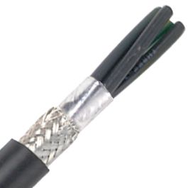
Ground / Drain wire

Learn the NEC with Mike Holt now!
Status
Not open for further replies.

LincHawk

Member
Location
Southeast
I had some questions about interpretations for drain wires in shielded cables. Is it common to use the drain in the control circuit as the ground on the ground terminal? Or should we have a separate conductor as the ground in addition to the drain wire?

What’s the standard method for this in industrial control wiring?


Sent from my iPhone using Tapatalk
 

tom baker

First Chief Moderator
Staff member
The shield is only connected at one end. Connecting at both ends can cause noise issues. SOP for me was to bond at the end where the cable got power.
For 24 V DC a EGC is not required most of the time, and a #14 is adequate.
 
  • Like
Reactions: sii

LincHawk

Member
Location
Southeast
What are you hooking up? What do you mean by ground?

The drain wire in a shielded cable is usually not used for ground if by that you mean an equipment ground. All the panels I have worked on the drain is connected at one end only in the panel.

24 vdc circuits to instrumentation devices


Sent from my iPhone using Tapatalk
 

LincHawk

Member
Location
Southeast
The shield is only connected at one end. Connecting at both ends can cause noise issues. SOP for me was to bond at the end where the cable got power.
For 24 V DC a EGC is not required most of the time, and a #14 is adequate.

So if an instrument has a ground screw do I need to run a separate ground wire to it? Or can I just connect the shield to that and not at the panel? This is a 24 vdc circuit


Sent from my iPhone using Tapatalk
 

ActionDave

Chief Moderator
Staff member
Location
Durango, CO, 10 h 20 min from the winged horses.
Occupation
Licensed Electrician
There is a transmitter that takes 120v and has return 24vdc to panel and two
Other 24vdc circuits to other devices. Everything else is straight 24vdc


Sent from my iPhone using Tapatalk

Then the 120V power needs some kind of equipment ground run with it to carry any fault current and sized ah la art. 250 of the NEC. The drain wire from a 24V control cable is no substitute.
 

Jraef

Moderator, OTD
Staff member
Location
San Francisco Bay Area, CA, USA
Occupation
Electrical Engineer
Then the 120V power needs some kind of equipment ground run with it to carry any fault current and sized ah la art. 250 of the NEC. The drain wire from a 24V control cable is no substitute.

Correct. As said earlier, instrument cabling shield drain wires should only be grounded at ONE END, preferably the source end. So even if is is of adequate size, if it is only grounded at one end it cannot function as an Equipment Grounding Conductor if you need one.

Shielded POWER cables must be grounded at BOTH ends because the shielding is for a different reason. But even then, the drain wire is not going to be sufficient as an EGC because in power cables that need shielding (ie VFD cables), the EGC must be at least the same size as the power conductors. That’s not in the code directly, but it will be in the installation requirements for the equipment, so it falls under 110.3.B.
 

drcampbell

Senior Member
Location
The Motor City, Michigan USA
Occupation
Registered Professional Engineer
If a cable is carrying low-level analog signals, the shield drain wires should be grounded at only one end. This is to prevent even a little bit of current from flowing, because current flowing in the drain wire or shield can couple into the small-signal wires and corrupt the signal. When it's connected at only one end, it serves as a Farady cage to isolate the small-signal wires from outside interferences.

... Shielded POWER cables must be grounded at BOTH ends because the shielding is for a different reason. ...
Don't keep us guessing. What's the reason?
 

hbeery10

Member
Location
Sardis, Ohio
Just to add to what's already been said, when we terminate the field end of a shielded low voltage cable make sure to tape over any exposed shielding or drain wire after it's been cut off so it doesn't come in contact with a grounded surface.


Sent from my iPhone using Tapatalk
 

Jraef

Moderator, OTD
Staff member
Location
San Francisco Bay Area, CA, USA
Occupation
Electrical Engineer
If a cable is carrying low-level analog signals, the shield drain wires should be grounded at only one end. This is to prevent even a little bit of current from flowing, because current flowing in the drain wire or shield can couple into the small-signal wires and corrupt the signal. When it's connected at only one end, it serves as a Farady cage to isolate the small-signal wires from outside interferences.


Don't keep us guessing. What's the reason?

In VFD output power cables, the shielding is still a Faraday Cage, but you are wanting to stop the RFI/EMI from getting OUT of the cables and since that signal is more powerful, you need it to have as short of a path to ground as possible, hence grounding both ends.

Output cables coming from a VFD are local radio broadcast antennas. Think about what FM means in radio; Frequency Modulation. Now think about what a VFD is doing in order to change the motor speed; modulating the frequency.

(To the purists out there this of course is a gross simplification of a complex situation, I’m just using it to illustrate the point.)
 

SSDriver

Senior Member
Location
California
Occupation
Electrician
I know this is an older thread but how do you properly bond the shield on both ends of VFD cable that doesn't have a drain wire (or common method). I had a customer order some Lapp SLIM VFD cable that will be installed in PVC conduit and I don't believe it has a drain wire. I could be wrong but it doesn't seem to mention it in the specs.


GeorgeB

ElectroHydraulics engineer (retired)
Location
Greenville SC
Occupation
Retired
I had a customer order some Lapp SLIM VFD cable that will be installed in PVC conduit and I don't believe it has a drain wire.
We would have either connected the braid to a terminal block directly, or to a wire "by approved means" then to a terminal block. The length of this should be kept to a minimum. In my designs with 4 conductor shielded, there were 5 adjacent terminal blocks.
 

SSDriver

Senior Member
Location
California
Occupation
Electrician
We would have either connected the braid to a terminal block directly, or to a wire "by approved means" then to a terminal block. The length of this should be kept to a minimum. In my designs with 4 conductor shielded, there were 5 adjacent terminal blocks.
Thanks, What is the approved method of connecting the braid to a terminal block? Do you just twist it in the shape of a wire?
 

GeorgeB

ElectroHydraulics engineer (retired)
Location
Greenville SC
Occupation
Retired
Thanks, What is the approved method of connecting the braid to a terminal block? Do you just twist it in the shape of a wire?
for us, it depended on the customers' specifications, but left to us, yes, just twisted. We had 2 who required a crimp connection to a green stranded #16; I see nothing gained except their green preference. I preferred SHORT over color. We used a grounding (green/yellow) block with 2 blocks on either side. Less than 1 inch of unshielded exposed on each side of the block.
 

MD Automation

Senior Member
Location
Maryland
Occupation
Engineer
Thanks, What is the approved method of connecting the braid to a terminal block? Do you just twist it in the shape of a wire?

There are several ways to connect / bond that braid in a VFD or Servo motor cable.

Here are 2 pics of some old motor cables I found quickly in the shop. The first is from a B&R Servo motor and might be sort of unique to that product. There is a metal finger that is screwed to the bottom of the drive and then the exposed braid is secured to the finger with a clamp.

1K8A0309_1.JPG

Next is another motor cable (this one to an older Lenze Servo) where you strip back and expose a section of the shield. Then you can use any of several different kinds of clamps to connect that exposed braid to a DIN rail or bar clamp (both grounded to a cabinet back plane). At least in my experience, we almost never twist that braid into a wire – we leave it exposed around the cable and grab it under some kind of fitting that squeezes down for good connection.

1K8A0311_1.JPG

Using something like these products...

1625675171075.png

Phoenix / Icotek and many other companies make these kind of spring or screw clamps. Just google “motor cable grounding clamp DIN rail” and you will find lots of hits on places like Digikey / Mouser / Automation Direct / Allied, etc that let you clamp down a braid to a DIN rail or grounding bar.

Good luck - hope any of this helped.
 
Status
Not open for further replies.
Top