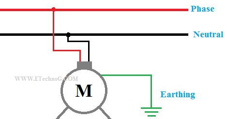
Ground: The Earth

Status
Not open for further replies.
This website was linked to on this forum in the past:
This is " Supposed " to be an ? Engineering Forum?
Possibly located in India.
Apparently they do not have the same understanding as in the USA and NEC.


He doesn't even have the same understanding as the IEC (Indian Electrical Code which is based off of IEC 60364).

Laymen from Professionals thinking that a ground rod will open a fuse or thermal magnetic breaker is fallacy encountered in almost every corner of the planet.

Mike's battle is very real, and very painful. He deserves all the support he can get.
 
Why does the earth have to be there for the fault path to be effective?

The purpose of making the connection to the Earth, is to establish a reference for the electrical system, so that the grounded conductor, equipment grounding conductor, and all electrically inactive metal are at the same absolute voltage as the surrounding terrain. Such that standing on the terrain and touching the metal housing of equipment, doesn't cause a dangerous shock.

No current should flow through the grounding electrode, and it should not be depended upon as an effective ground-fault current path. The contact resistance of the electrode in the terrain has too many ohms to effectively trip a breaker under fault conditions. The EGC is necessary to provide a ground fault current path back to the source.

False.

Resistance = rho / distance.

Rho is specific resistance of the soil (ohm-feet or ohm-meters). This is the “high” value you are speaking of.

At some point (about 1-2 miles) resistance gets to be much lower than a copper ground wire or even conduit.

Edison’s original DC dynamo distribution system was a one wire system. The returns were ground rods. Granted there were lots of problems with it but it shows that a ground is very effective.

“Stray voltage” (current) would simply not exist if what you are saying was true.

IEEE green book (grounding) explains this concept in detail.

Have you ever actually measured ground resistance? What happens if you get the reference electrode too far away?
 
Carultch's statement is not _false_, but rather applicable to a limited domain. In particular it is very much applicable to the voltages and structure sizes encountered by electricians working in buildings.

If you stick a couple of 8 foot long copper rods into the soil, and connect a 277V 'hot' to those rods, it is unlikely that you will trip a 20A breaker. You will kill a bunch of worms, cook some soil, and likely create lethal 'step potentials' in the soil, but you will not trip the breaker.

On the other hand, at utility distribution voltages and distances, the earth is often an effective ground fault path. SWER systems exist and function, and my understanding is that some of the large HVDC links are designed with + and - conductors, with ground electrodes that can be used to maintain 1/2 capacity if one or the other polarity lines go down.

I read the comment that ' No current should flow through the grounding electrode ' as meaning that one should not arrange electrodes to intentionally carry current, no to be used as a ground fault path. It is certainly the case that grounding electrodes can carry current, and that stray voltage is a problem when multi-point grounded systems inject current into the soil.

-Jon
 
Then why do uni grounded system behave more and more like ungrounded systems heading away from the substation?

Just because the ground fault path impedance is zero, that does not mean the phase conductor path is also zero.

Second for small conductors #10 and smaller resistance dominates. Above that size reactance dominates. So as the system length increases Z0 is relatively fixed (X/R not increasing) but since the time delay is however increasing eventually we get ringing (oscillations).


But how does the explain the sharp rise in R? Uni grounded systems act totally ungrounded several miles out.
 
I read the comment that ' No current should flow through the grounding electrode ' as meaning that one should not arrange electrodes to intentionally carry current, no to be used as a ground fault path. It is certainly the case that grounding electrodes can carry current, and that stray voltage is a problem when multi-point grounded systems inject current into the soil.

-Jon

Also since we're being very picky here, another purpose of an "Earthing" electrode is to drain naturally induced voltages. Not just lightning but wind can also create static electrical charges. So in that respect current most certainly should flow through the grounding electrode, but it will also be fairly intermittent.
 
Also since we're being very picky here, another purpose of an "Earthing" electrode is to drain naturally induced voltages. Not just lightning but wind can also create static electrical charges. So in that respect current most certainly should flow through the grounding electrode, but it will also be fairly intermittent.

Then why do ungrounded systems not flash their arrestors?
 
But how does the explain the sharp rise in R? Uni grounded systems act totally ungrounded several miles out.

Simple. When a transient such as when we have a fault hits the end of the cable it is reflected. Since the fault impedance is nearly zero, the reflected wave MUST equal the incoming wave so it is equal in amplitude but opposite in polarity. The reflected wave travels back along the cable and reflects again off the source, to return again over and over until it dissipates at the source end. While it travels down the cable it is effectively unchanged or a least that's how we model it. If the cable length gets long enough then the reflected wave will be delayed to the point where the sum of the reflected wave voltages equals or exceeds the source voltage. Thus transient voltages can grow quite large.

This is all basic transmission line theory. The same thing happens for any type of fault (line-ground, line-line, 3 phase, double line to ground). It happens any time that the wiring is no longer "electrically short" to where Z0 is such a small value that we can effectively ignore it.

At 60Hz? This would hold true for lightning.
 
Then why do ungrounded systems not flash their arrestors?

For the obvious reason that at least on the first ground fault if it's of the bolted type, you just converted the system into a corner grounded delta. There may be stored charge but it is conducted harmlessly away.

In an arcing fault, we get an unusual situation. In that case the arcing fault "pumps" the system capacitance causing it to grow to theoretically infinite voltage. It never gets there because eventually something flashes over to stop it. If there are surge arrestors, those operate to prevent voltage from rising any further. If there are no surge arrestors it continues to rise until it destroys something. Typically motors and generators have the weakest insulation of all so those become your "surge arrestors" and are destroyed prematurely.

Doesn't answer my question.

Why don't ungrounded systems flash their arrestors on windy days?
 
Status
Not open for further replies.
Top