muddyboots
Member
- Location
- Florida
- Occupation
- Electrician
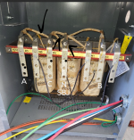
I have a 3 phase 45 kva, step down, 480 delta to 240/120 high leg delta with a center tap nuetral, and I'm a little confused with regard to grounding and bonding.
Xfmr Primary: 70A 3ph (Cu)3-#4 + #8 EGC.
Xfmr Secondary: 150A 3ph (Al)4-2/0 + #2 SSBJ
GEC: (Cu) #4
This is one of many step down xfmrs at a new construction, production facility, with GECs being bonded to the grounding system through building steel.
One thing that's throwing me off is the riser diagram is calling for 3ph 4 wire, but the panel schedule is calling for 3ph 3 wire, which, that may be neither here nor there.
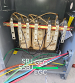
I have my primary EGC bonded to transformer case, and my secondary SSBJ bonded to the transformer case. Does the GEC bond to the transformer case as well? Or does it have to terminate to x-4? Similar to how you would terminate your GEC to x-0, in a typical step down 480 delta to 208/120 wye xfmr, with a bonding jumper bonded to xfmr case?
The buss on the x-4 is sized to only accommodate one lug, which seems to indicate there is no bonding jumper. Is there even a nuetral ground bond required on this type of system, being that it's separately derived? Is that taken care of internally? Is the nuetral even a "grounded conductor" in a center tap high leg delta system? If this were to be a corner grounded high leg delta transformer, what would be different? Am I even in the ballpark?
Regardless I appreciate any advice and insight you guys may be able to provide me, and I appreciate you taking the time out your day. I hope this is an appropriate thread for this forum and doesn't veer too far off topic. Thanks again. P.S. I Tried to upload a picture to this post not sure if it made it through though.
~muddyboots
Xfmr Primary: 70A 3ph (Cu)3-#4 + #8 EGC.
Xfmr Secondary: 150A 3ph (Al)4-2/0 + #2 SSBJ
GEC: (Cu) #4
This is one of many step down xfmrs at a new construction, production facility, with GECs being bonded to the grounding system through building steel.
One thing that's throwing me off is the riser diagram is calling for 3ph 4 wire, but the panel schedule is calling for 3ph 3 wire, which, that may be neither here nor there.
I have my primary EGC bonded to transformer case, and my secondary SSBJ bonded to the transformer case. Does the GEC bond to the transformer case as well? Or does it have to terminate to x-4? Similar to how you would terminate your GEC to x-0, in a typical step down 480 delta to 208/120 wye xfmr, with a bonding jumper bonded to xfmr case?
The buss on the x-4 is sized to only accommodate one lug, which seems to indicate there is no bonding jumper. Is there even a nuetral ground bond required on this type of system, being that it's separately derived? Is that taken care of internally? Is the nuetral even a "grounded conductor" in a center tap high leg delta system? If this were to be a corner grounded high leg delta transformer, what would be different? Am I even in the ballpark?
Regardless I appreciate any advice and insight you guys may be able to provide me, and I appreciate you taking the time out your day. I hope this is an appropriate thread for this forum and doesn't veer too far off topic. Thanks again. P.S. I Tried to upload a picture to this post not sure if it made it through though.
~muddyboots