grounding center tap 12kv delta trans

Status
Not open for further replies.

Cold Fusion

Senior Member
Location
way north
--- Article 250 Part X does not supplement or modify any of the requirements of the previous Parts of Article 250.
Yes, that is the way I read 250.180 as well.

Unless it is established that the premises 12kV system has a neutral, Article 250 Part X does not ---
I don't see this as true. Here is an example:

Given the limited information we have, one might consider applying 250.182, and grounding the system. Although I don't really know, it is difficult to see the installation specifics from my side of the monitor.

As we all know:

The NEC does not give a receipe for premisis wiring over 1kv like they do for house wiring. There are no cookie cutter systems over 1kv

Grounded, un-grounded, ground detectors, relaying - all design/engineering decisions.

The code panels writing the over 1kv sections appear to know this.

cf
 
T2/t1

T2/t1

aretae (Gary),

Check the cut sheets again. The one you posted is more understandable as being "T-2", the step-down transformer.

There is a T2, it is one thousand seven hundred feet from the transformer in question. The 12kv secondary from T1 has become the primary for T2.

How would you accomplish a proper corner tap of a delta 12kv secondary and perform proper bonding?
 
How do it?

How do it?

Is it necessary to ground this 12kv delta secondary?
What would be the proper way of doing so?
Should an EGC be run with the feeders out to the next transformer?
 

Smart $

Esteemed Member
Location
Ohio
--- Article 250 Part X does not supplement or modify any of the requirements of the previous Parts of Article 250.
Yes, that is the way I read 250.180 as well.
If you're going to take this part of my statement out of context, Article 250 Part X does supplement and/or modify the requirements of the previous Parts of Article 250.

Unless it is established that the premises 12kV system has a neutral ---
I don't see this as true. Here is an example:

Given the limited information we have, one might consider applying 250.182, and grounding the system. Although I don't really know, it is difficult to see the installation specifics from my side of the monitor.
What my full statement means is that for the situation as described by the OP'er (and my understanding thereof), there is no neutral that could be grounded on the 12kV secondary. Article 250 Part X is for grounding neutrals, and mobile or portable systems over 1kV. The situation as described does not have any of these parameters.

As we all know:

The NEC does not give a receipe for premisis wiring over 1kv like they do for house wiring. There are no cookie cutter systems over 1kv

Grounded, un-grounded, ground detectors, relaying - all design/engineering decisions.

The code panels writing the over 1kv sections appear to know this.

cf
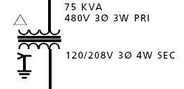
I completely agree with you here.
 

Smart $

Esteemed Member
Location
Ohio
There is a T2, it is one thousand seven hundred feet from the transformer in question. The 12kv secondary from T1 has become the primary for T2.
...
I'm aware of this.

I'm thinking somewhere in the design process the configuration of T-1 and T-2 got flopped. I see the one-line indicates an oil-filled xfmer for T-2... but I wondering what configuration the cut sheet shows for T-2???
...
How would you accomplish a proper corner tap of a delta 12kv secondary and perform proper bonding?
In my mentioning of corner grounding the secondary, I did not intend for you to take it as a recommendation. In this particular case I'll defer to a higher authority :rolleyes::grin:

Is it necessary to ground this 12kv delta secondary?
What would be the proper way of doing so?
Should an EGC be run with the feeders out to the next transformer?
No, it is not necessary (read as: required) to ground the 12kV system.

IMO, I would not ground the 12kV unless T-1's secondary windings are wye configured. If not grounded, the addition of ground-fault protective equipment would depend on the conditions of and along the run.

In either case, an EGC is not required. Most scenariios where I would be around such a system, all non-current carrying metal would already be bonded to a ground grid.
 
Flopped design

Flopped design

I'm aware of this.

I'm thinking somewhere in the design process the configuration of T-1 and T-2 got flopped. I see the one-line indicates an oil-filled xfmer for T-2... but I wondering what configuration the cut sheet shows for T-2???

Perhaps, but I think they planned it this way. I uploaded T2 specs.
 
Center/Corner

Center/Corner

It's not that clear to me :confused:

Winding configuration is neither stated explicitly nor schematically. I generally see it indicated similar to...

one-linexfmr.gif


But then there is the annotation...

one-lineannotation.gif


Who put it there? ...and what bearing does it have on the drawing???

I may have started calling it a center tap when I first saw the single line. I understand now it is properly called a ccorner tap. Is the symbol for both exactly the same?
 

jim dungar

Moderator
Staff member
Location
Wisconsin
Occupation
PE (Retired) - Power Systems
I may have started calling it a center tap when I first saw the single line. I understand now it is properly called a ccorner tap. Is the symbol for both exactly the same?
There are no standard symbols for transformer windings shown on a one line. Yes, there are common symbols (like the one posted by Smart) that may be used 'most' of the time, but 'most' is not 'always'. But, even the post by Smart does not follow the ANSI recommended convention of listing voltages (i.e. 208Y/120).
 
There are no standard symbols for transformer windings shown on a one line. Yes, there are common symbols (like the one posted by Smart) that may be used 'most' of the time, but 'most' is not 'always'. But, even the post by Smart does not follow the ANSI recommended convention of listing voltages (i.e. 208Y/120).

arrghhh...well, ok.... Since the ANSI convention is merely a recommendation I suppose there is no mandate to adhere to anything. Therefore, one would have to read all relative documentation to understand that that the tap is off a DELTA secondary and not a center-tapped wye as I first thought. As a mere electrician in the field, we could sure use one single drawing that tells us what is happening, or perhaps at least with notes or details clearly referenced.

Thanks Jim,
gary
 

Smart $

Esteemed Member
Location
Ohio
There are no standard symbols for transformer windings shown on a one line. Yes, there are common symbols (like the one posted by Smart) that may be used 'most' of the time, but 'most' is not 'always'. But, even the post by Smart does not follow the ANSI recommended convention of listing voltages (i.e. 208Y/120).

Good catch, Jim :)

FWIW, that symbol was "gleaned" from an example in NEiS Symbols For Electrical Construction Drawings [NECA 100-1999]. It can be purchased through ANSI's eStandards Store by clicking on the link.

The error appears to be on the person that made the example. The following is the symbol as listed:
one-linexfmr2.gif
 

Smart $

Esteemed Member
Location
Ohio
As a mere electrician in the field, we could sure use one single drawing that tells us what is happening, or perhaps at least with notes or details clearly referenced.
That's the EE's job, and many squeak by on the minimum (many don't ;)). Your situation needs cleared up by the engineer of record for the project.
 

Cold Fusion

Senior Member
Location
way north
--- As a mere electrician in the field, we could sure use one single drawing that tells us what is happening, or perhaps at least with notes or details clearly referenced.
As a mere field EE (PE), that same drawing would also be welcome by me. I'd even settle for enough on the drawing to be able to guess what the designer/house engineer had in mind.

But I still wouldn't recommend either of us squawk - we get paid to take the design drawings and make a working system. :rolleyes:

cf
 

Smart $

Esteemed Member
Location
Ohio
As a mere field EE (PE), that same drawing would also be welcome by me. I'd even settle for enough on the drawing to be able to guess what the designer/house engineer had in mind.

But I still wouldn't recommend either of us squawk - we get paid to take the design drawings and make a working system. :rolleyes:

cf

So what do you suggest Gary do? ;)
 
EE of record

EE of record

That's the EE's job, and many squeak by on the minimum (many don't ;)). Your situation needs cleared up by the engineer of record for the project.

I wish they would do so, it is worse than pulling teeth. The GC has forced us to provide our "interpretation" of how the grounding will be done, stating that the "criteria provided is enough to build from". The extensive drawing review by a bunch of competent electricians (none of us EE's) has spawned so many discrepancies between the single line and notes that everything is grinding to a halt.

EXAMPLE:

We noted only three wires in the 12kv pull and RFIed to make sure no EGC to be pulled in, this was confirmed. The grounding detail shows the metal enclosures at each end bonded with an....... EGC. Now we have to RFI if they want the shield used as an EGC. Guess what, no detail on shield terminations at either end, just landings on a ground rod in each vault. Plus, it is sorta a moot point, we do not think the shield is ever used for equipment grounding, the code states to protect the insulation from corona effects. Yes?

aretae
 
As a mere field EE (PE), that same drawing would also be welcome by me. I'd even settle for enough on the drawing to be able to guess what the designer/house engineer had in mind.

But I still wouldn't recommend either of us squawk - we get paid to take the design drawings and make a working system. :rolleyes:

cf

lol....a "mere field EE (PE)"....yes. I would love to have the knowledge a PE in the EE field has. Anyway, this EE has taken offense at our asking questions we cannot answer. Sheesh, if you would welcome this, please come over and figure it out :)
 

Smart $

Esteemed Member
Location
Ohio
I wish they would do so, it is worse than pulling teeth. The GC has forced us to provide our "interpretation" of how the grounding will be done, stating that the "criteria provided is enough to build from". The extensive drawing review by a bunch of competent electricians (none of us EE's) has spawned so many discrepancies between the single line and notes that everything is grinding to a halt.

EXAMPLE:

We noted only three wires in the 12kv pull and RFIed to make sure no EGC to be pulled in, this was confirmed. The grounding detail shows the metal enclosures at each end bonded with an....... EGC. Now we have to RFI if they want the shield used as an EGC. Guess what, no detail on shield terminations at either end, just landings on a ground rod in each vault. Plus, it is sorta a moot point, we do not think the shield is ever used for equipment grounding, the code states to protect the insulation from corona effects. Yes?

aretae
The shield it is not an EGC, IMO. But then again, it is a grounding conductor and 99% of the MV/HV installations I've been on did not run a separate EGC (i.e. in addition to the conduit or cable tray). I have also seen it used as parallel neutrals. Not saying it's right... just that I've seen it done.

I would offer my opinion on how to install it... but then you'd just have another discrepancy from another competent electrician ;):grin:

The only other avenue I can suggest is to ask the AHJ for the method they will approve.
 
AHJ hired and EE

AHJ hired and EE

The shield it is not an EGC, IMO. But then again, it is a grounding conductor and 99% of the MV/HV installations I've been on did not run a separate EGC (i.e. in addition to the conduit or cable tray). I have also seen it used as parallel neutrals. Not saying it's right... just that I've seen it done.

I would offer my opinion on how to install it... but then you'd just have another discrepancy from another competent electrician ;):grin:

The only other avenue I can suggest is to ask the AHJ for the method they will approve.

The AHJ hired an engineer to review this. It was s/he who mandated the ground.
 

Cold Fusion

Senior Member
Location
way north
So what do you suggest Gary do? ;)
Hummm.... That's a pretty tough question from my side of the keyboard. And I'm pa2b - which doesn't always make for good answers.:)

I went back over the posts to check the criteria.

The GC has forced us to provide our "interpretation" of how the grounding will be done, stating that the "criteria provided is enough to build from".
That's an major ouch. Every response that comes to mind isn't acceptable in polite company. "Excuse me, they are the engineers, we are the craft. The engineer of record comes up with the 'interpretation'; we put in the bolts. Even so, we are team players, if we knew of an industry standard installation method that was even close, we would suggest it in a second. There isn't one that fits what they are saying"

You are going to have a hard time making chicken soup out of this one. Okay, moving on:

The system is:
480V feeding a 500kva, 480Y/12460D xfm.
Three shielded conductors from xfm1 to xfm2
Xfm2 is a 500kva, 12460D/480Y
xfm secondary FLA (12460V side) is ~23A
Secondary fuses are 65E

"They" (AHJ?) want:
1. An EGC between the two transformers.
2. The 12460v system is to be grounded.

Engineer says:
1. Ground xfm1 12460V "centertap" (The "centertap" issue is a problem, but aside from that, separate ground rod - that is not connected to xfm case? I'm assuming there is an EGC from the 480V feeder source to xfm1 case)

2. Use the 12460V shields for the EGC. (Smart $ had a good comment here ? Is there a metallic conduit, cable tray, or cable sheath between the two xfms?)

Some guesses and observations:
Conductors are #2 (probably the smallest you can easily buy)
Shield grounds are #12
At 5% impedance that gives <500A SSC
At 400A, 65E fuses will blow in 1 - 2sec. Makes one wonder how long a cable shield, by itself, would last at 400A.

Smart $ had another good comment: ?? ask the AHJ for the method they will approve?

Gary - jump in here, verify, correct, or add. I?m pa3b now. I?ll look at it again after you respond.

cf


Status
Not open for further replies.
Top