Group Motor Installations - Everyone Questions My Wire Size

Status
Not open for further replies.

cowski

Member
Location
New York
Occupation
Engineer
We build industrial control panels with 1-4 motors.

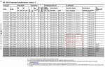
I size the wires in our panel per NEC 430.24. A few times people have called me out on this, complaining that the wire ampacity is less than the overcurrent protection. This is doesn't apply to motors, right? A 15HP motor would be protected by a 50A inverse time circuit breaker (21*2.25=47.25 -> 50 inverse time CB). Wire gage would be 10 (125% of 21A).

A PE once emailed me this:
"Code requires small conductors to be protected by the upstream circuit breaker of the same ampacity or lower."
He must have been referencing Article 310, right? And article 430 would override that.

Anyway, it's frightening to me how often people aren't aware of NEC 430.24. Is it common to ignore this, and upsize motor conductors? Or are they looking at my control panel like a black box, and not thinking about the motors being powered inside? Should I just upsize my motor conductors to match OCPD? I've talked with other panel shops that seem to do this.

Finally - I size branch circuit protection per the VFD's recommended values. For a 15 HP A/B drive, they list a 60A Class T fuse. Installers always want to know which circuit breaker to use, so I recommend 2.25*21 (FLA of a 15 HP motor) which gives 50A. So I have a 50A inverse time breaker in the wall connected to 60A type T fuses with 10 AWG (seemingly underrated for both). Does this make sense? Or should I simply upsize my wire ampacity to match the recommended circuit breaker?
 

bwat

EE
Location
NC
Occupation
EE
It seems like there might be two different questions here.

For the first part, you also include overloads for each motor as per Part III of article 430, right? See something like 430.32. A 15HP motor started across the line with simply a 50A breaker upstream would not be compliant. It needs overload protection.

For the part about VFD, which might be a separate question, see Part X of 430. Something like 430.122. Conductors to VFD to be at least 125% of VFD rated input, not motor rating.

If you could include a sketch of the circuit you’re asking about it would help clarify.
 

cowski

Member
Location
New York
Occupation
Engineer
Right. See attached sketches, and thanks for your help. There's a single and multi motor design.

I'm relying on the VFDs for overload protection per 430.124(a). They cannot provide short circuit protection, so I'm using Type T fuses as specified in the VFD manual (also attached) and per 430.130(a)(4) which allows type T fuses assembled with the VFD. On the rare occasion we supply a motor without a VFD I use a UL type E combination manual motor starter.

And yes. thank you for reminding me that motors controlled by VFDs require conductors to be sized per 430.122. In my experience the VFD rated input has led to the same wire gage as 1.25*FLA of the motor but I need to correct that thinking in my head...(and my design calculations!!!)

For multi-motor installations, my approach to OCP has been to place each VFD on its on branch circuit. That makes the wires coming into the panel a feeder, right? Is this acceptable under all conditions or do I need to know what's "upstream" of my panel? It's typically a dedicated inverse time breaker in a panelboard. I'm often asked what size breaker and then questioned when the inverse time rating of the breaker is above my wire ampacity.
 

Attachments

  • singlemotor.pdf
    22.8 KB · Views: 12
  • multimotor.pdf
    39.6 KB · Views: 16
  • 1.jpg
    1.jpg
    538 KB · Views: 13

Eddie702

Licensed Electrician
Location
Western Massachusetts
Occupation
Electrician
Sounds to me like your fine. Your right a lot of people don't understand the motor overload protection, wire size and over current protection for motors. Even electricians who have years in the field don't understand it.
 

petersonra

Senior Member
Location
Northern illinois
Occupation
engineer
We are a UL508a panel shop. Many of our panel wirers do not understand the wire sizing and overcurrent protection device sizing rules. Some of our engineers just make the wire size based on the over current protection device size so they don't have to answer the question over and over again. Personally I usually make the over current protection device as large as I can to avoid nuisance trips, plus I sort of like having it really big with a relatively small wire coming out of it. :)
 

bwat

EE
Location
NC
Occupation
EE
To the OP: I think your general concept is good, but you may need a couple adjustments where you used the motor rating rather than vfd input rating. See posts 2 and 3. I don't think you're achieving 125% of VFD input rating for your conductors if you're to be using table 28.1 from UL508A, and it sounds like you're providing listed equipment if you're citing 430.130(a)(4).

Other than that, it seems right.

When someone gives you a hard time about not being protected at ampacity, show them these (my bold):

240.4 Protection of Conductors. Conductors, other than flexible
cords, flexible cables, and fixture wires, shall be protected
against overcurrent in accordance with their ampacities specified
in 310.15, unless otherwise permitted or required in
240.4(A) through (G).

and

(G) Overcurrent Protection for Specific Conductor Applications.
Overcurrent protection for the specific conductors shall
be permitted to be provided as referenced in Table 240.4(G).
(article 430 for motors is listed in Table 240.4(G))
 
Status
Not open for further replies.
Top