Harmonics?

Status
Not open for further replies.

iwire

Moderator
Staff member
Location
Massachusetts
pbeasley said:
Brian John, Try reducing current on any one leg to zero amps and see how your neutral is loaded. Harmonics are not the only reason to carefully evaluate neutral sizing.

If you remove harmonics from the question there is NO WAY to overload the neutral following the NEC minimums. I also don't think your giving Brian the credit his experience commands. :smile:

There have been some instances of neutral overloading on both temporary and permanent installations of SCR/SSR based Dimming control systems. The idea being that in Live Entertainment it is extremely difficult to maintain a balanced load through out a performance....

Now I have no doubt that can be a problem, but it has nothing to do with the OPs question and that is why those installations get their own code sections.
 

brian john

Senior Member
Location
Leesburg, VA
The idea being that in Live Entertainment it is extremely difficult to maintain a balanced load through out a performance and even if it is relatively balanced, the loads are almost never running at full voltage, the waveform is usually being chopped ALOT and the harmonics can be amazing

I THINK I said neutral harmonic issues are possible. BUT in a typical office building with standard everyday off the shelf ballast, in my experience neutral currents higher than phase currents have not been found. They may exist, and I would like to be involved in jobs with these issues, I like dealing with the unusual, I have had to deal with myself all my life.

On the one waveform I posted, this was an extreme case with a mix of old and new electronic equipment. The neutral current matched the phase currents. Not necessarily a good situation as there is additional heating associated with harmonics, but the neutral in this case sized for the load on the system was adequate for the job.
 

crossman

Senior Member
Location
Southeast Texas
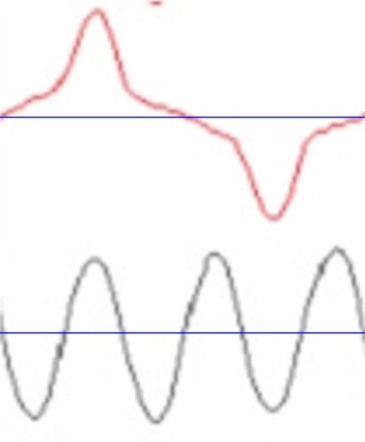
In the following diagram posted by brian john, it sure looks to me that the RMS neutral current would be alot higher than the phase currents. Can anyone explain why In would be about the same as Ia?

brian john said:
HARMONICS1.jpg
 

crossman

Senior Member
Location
Southeast Texas
Here is a close-up:

At the moment, I just can't see that the red wave at top would have about the same RMS value as the black wave at bottom. I would guess the bottom wave RMS value is about 2+ times larger than the top wave.
harmonic.jpg
 

ELA

Senior Member
Occupation
Electrical Test Engineer
brian john said:
I have had to deal with myself all my life.

Me too! Aint it a bitch...

Sorry brian but I could not resist that one :smile:


On Crossmans question, are those waveforms on the same scale?
It appears that the numbers on the bottom are the calculated RMS values?
 
iwire said:
If you remove harmonics from the question there is NO WAY to overload the neutral following the NEC minimums. I also don't think your giving Brian the credit his experience commands. :smile:

Good point... and re-reading my post I think I was PWT (posting while tired), sorry if any offense was taken.
 

crossman

Senior Member
Location
Southeast Texas
I just did some rough calculations on the sine waves from brian john's graph. I am assuming each graph is using the same scale. Yes, assuming! Inspecting the phase waves and the neutral wave gives me reason to believe they are all using the same scale.

The neutral sine wave shown in the graph has a slightly lower peak than the phases. This is reasonable because there is some phase current which is being shared among phases, but a good portion of the phase currents, especially near the peaks, is not being shared on phases and must return on the neutral.

My rough calculations indicate that with approx 220 amps RMS on the phases, the neutral would have 353 RMS amps on it, not the 212 as shown on the original graph.

In the interest of sparking some dialogue which may promote my electrical education, I am going to say:

Brian John, your fancy meter is broken or is not set on the proper scales/values.
 

brian john

Senior Member
Location
Leesburg, VA
Cross:

I always question my meters, when readings seem off.

What we did.

Comparison readings to the meters on the UPS, utilized a FLUKE 123, and a fluke true RMS amp clamp.

All were within acceptable percentages, and while errors are MADE, we always use calibrated meters.

I will check the report file for the copy and review.
 

crossman

Senior Member
Location
Southeast Texas
Thanks for the reply, brian john.

I am just baffled that the two waves in the blow-up diagram above could have approximately equal RMS values, and would like to know why your meter shows such.
 
this topic has got me thinking. If I wanted to do some field measurements on an existing install would I get equivalent readings for these 2 scenarios...

-Circuits 1,3,5 as a MWBC using clamp-meter on grounded conductor
-circuits 1,3,5 with seperate gounded conductors using clamp meter on all 3 grounded conductors.

My thinking is the readings would be similar but not exactly the same. Am I off base?

edit to correct spelling
 
Last edited:

76nemo

Senior Member
Location
Ogdensburg, NY
pbeasley said:
this topic has got me thinking. If I wanted to do some field measurements on an existing install would I get equivalent readings for these 2 scenarios...

-Circuits 1,3,5 as a MWBC using clamp-meter on grounded conductor
-circuits 1,3,5 with seperate gounded conductors using clamp meter on all 3 grounded conductors.

My thinking is the readings would be similar but not exactly the same. Am I off base?

edit to correct spelling

No, you are correct. Why would they be different?
 

winnie

Senior Member
Location
Springfield, MA, USA
Occupation
Electric motor research
pbeasley said:
-Circuits 1,3,5 as a MWBC using clamp-meter on grounded conductor
-circuits 1,3,5 with separate grounded conductors using clamp meter on all 3 grounded conductors.

My thinking is the readings would be similar but not exactly the same.

I think that there would be a _slight_ difference in the two readings because of the different conductor resistances between the two approaches, but that the readings would be essentially the same.

-Jon
 

crossman

Senior Member
Location
Southeast Texas
winnie said:
I think that there would be a _slight_ difference in the two readings because of the different conductor resistances between the two approaches, but that the readings would be essentially the same.

Okay Winnie, but what about the RMS values of the diagram that brian john posted?:-?
 

wptski

Senior Member
Location
Warren, MI
brian john said:
Cross:

I always question my meters, when readings seem off.

What we did.

Comparison readings to the meters on the UPS, utilized a FLUKE 123, and a fluke true RMS amp clamp.

All were within acceptable percentages, and while errors are MADE, we always use calibrated meters.

I will check the report file for the copy and review.
How were the waveforms in Post #6 put together? It shows five channels and the Fluke 123 only has two.
 

crossman

Senior Member
Location
Southeast Texas
Those indicated values must have been taken simply by multiplying the peak x .707 for a sine wave. This method does not work for a non-sinusoidal wave like the phase graphs.

In a balanced, pure triplen three-phase circuit, the neutral RMS current will be 3 times the phase RMS current.
 

wptski

Senior Member
Location
Warren, MI
crossman said:
Those indicated values must have been taken simply by multiplying the peak x .707 for a sine wave. This method does not work for a non-sinusoidal wave like the phase graphs.

In a balanced, pure triplen three-phase circuit, the neutral RMS current will be 3 times the phase RMS current.
You can calculate exact measurements from a scope using it's grids but none are shown here. The current waveform doesn't appear to have a CF greater than 3-3.5 by looking at it, so a True RMS meter ought handle that correctly.
 

gar

Senior Member
Location
Ann Arbor, Michigan
Occupation
EE
080515-1948 EST

Suppose I make the current a short rectangular pulse. For this example duration is 0.0083 seconds (1/10 of 1/2 cycle) and there is one pulse of amplitude 10 A per half cycle per leg. Per pulse by observation this has an RMS value of 3.16 A. Square it, average, and the sq-root. Since there are 3 equally spaced non-overlapping pulses per half cycle from the 3 legs the RMS value for the 3 is = 3 times the above average (30) and the sq-root of 30 = 5.48 or the sq-root of 3 times the single pulse RMS value.

The above calculation is done as follows: Square the pulse current. This result is proportional to the power dissipated in a resistor. Since the power lasts for only 1/10 of the period the average power is proportional to 1/10 of the current squared. To convert this back to a continuous current over the entire time period we take the square root of that average.

When we combine the 3 pulses without overlap the average power increases by 3, then take the sq-root of this 3 times larger average and the result is 1.732 * RMS of one pulse.

When there is overlap of the 3 different pulses, then the neutral RMS value will diminish.

.
 
unbalance and harmonics

unbalance and harmonics

noutral wire may has double current of live wire through 2 things:
1- if the load is rich with 3rd harmonics.
2- if L1 feed high inductive load and L2(-120) feed high capacitive load and L3 has zero or minor current.
 
Status
Not open for further replies.
Top