Having trouble understanding current in Delta load.

Status
Not open for further replies.
Before i start i want to make it clear that i do understand the 120 degree phase shift dissplacment between each phase, i do have basic understanding of wye delta systems and the voltage current differences between them example (square root of 3,1.732) I do very well understand why the square root of 3 expresses the voltage and current differences. (Sounds like I'm controdicting myself I know :ashamed1:)

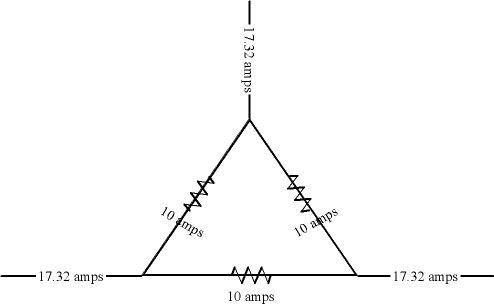
I might be reading into this a bit to much and creating issues that do not exist, but I have been struggling with current flow specifically in a delta connected load. Im not concerned with what type of loads (resistive,capacitive,inductive). If we have a 3 phase Transformer connected delta and a load that is connected delta, why is it if all 3 phases in the load are drawing and equal amount of current lets say 57amps the line amperage will be greater by the square root of 3.? Let me just say this, I understand a wye connected secondary systems voltage differences, lets say a wye system has a coil voltage of 120v across each phase, I then measure the voltage across 2 phases I would be measuring the square root 3 so 208v. I also understand the current in a wye system will be same across each phase opposed to the line, makes perfect sense!!

But for the life of me I can't get this through my head concerning a delta system, I understand that at any period of time in a balanced 3 phase system current / voltage will never be at its maximum value at once and at other times will be divided between only 2 phases.

Example - at one point in time phase A will be at its most positive peak, phase B & C will be in there negative direction but less then maximum. Another point in time phase A will now be zero and phases B&C will be of opposite polarity but less then maximum. This is why it will be impossible to add the sum of two coils voltage lets say.

Someone please help me with this. :slaphead:
 

Smart $

Esteemed Member
Location
Ohio
So you are familiar with waveforms of 3?. Let's build on that. We have a delta connected load consisting of three line-to-line connected loads: AB, BC, CA. To discuss phase relationships, the voltage across one of the three has to be our 0? reference. It is commonly C to A... then A to B lags by 120?, and B to C lags by another 120?...

waveforms1_zpsa2ddbf6c.gif


The depicted waveforms reresent the three line-to-line voltages. Purely resistive loads' currents follow the voltage, so the depiction can be said to represent the three line-to-line load currents also. Now let's discuss how the currents combine at connection to Line A. The brown waveform depicts current at A as referenced to C, while the orange waveform depicts current at B referenced to A. To sum currents at A, we need to have the orange waveform represent current at A referenced to B, i.e. opposite what is depicted. To do this we simply have to invert the waveform, because its just being measured backwards, and as such, the current appears to be 180? of what it was measured the original way.

waveforms2-1_zpscaa6a88c.gif


Note the inverted waveform (dashed orange) does not lag C-A, but instead leads by 60? (halfway between B-C and C-A). Note the point where C-A and B-A cross. It is halfway between B-A and C-A peaks, i.e. ? and + 30? respectively. The value of each waveform at that crossing is equal to (cos 30?) times their peak value. Cos 30? = 0.8660, or (√3) ? 2. Those currents, C-A and B-A, add together: (√3) ? 2 + (√3) ? 2 = √3, which is the peak of the two currents added together on Line A. The red waveform depicts the summed currents through the entire cycle...

waveforms3-1_zps90c9f8d5.gif


Questions???? :p
 

hardworkingstiff

Senior Member
Location
Wilmington, NC
If we have a 3 phase Transformer connected delta and a load that is connected delta, why is it if all 3 phases in the load are drawing and equal amount of current lets say 57amps the line amperage will be greater by the square root of 3.?

I don't believe I can help you, but I don't understand what you are saying here.

You didn't state what the primary voltage and secondary voltage are. That makes it hard for my simple mind to understand the current issue you are stating.
 

Strathead

Senior Member
Location
Ocala, Florida, USA
Occupation
Electrician/Estimator/Project Manager/Superintendent
If we have a 3 phase Transformer connected delta and a load that is connected delta, why is it if all 3 phases in the load are drawing and equal amount of current lets say 57amps the line amperage will be greater by the square root of 3.? :slaphead:

If I am reading everything you wrote correctly, then the answer to your question is a head slapper. It is not an increase from 57 amps by the square root of three, it is decrease from 57 x 3 to 57 x 1.73.
 

david luchini

Moderator
Staff member
Location
Connecticut
Occupation
Engineer
If I am reading everything you wrote correctly, then the answer to your question is a head slapper. It is not an increase from 57 amps by the square root of three, it is decrease from 57 x 3 to 57 x 1.73.

:? The load (phase) currents are all 57A. The line currents are all 98.7A This is an increase by the square root of three (57 * 1.732 = 98.7)

57A * 3 = 171A, which has nothing to do with the system in the example?!?!
 

kwired

Electron manager
Location
NE Nebraska
If we have a 3 phase Transformer connected delta and a load that is connected delta, why is it if all 3 phases in the load are drawing and equal amount of current lets say 57amps the line amperage will be greater by the square root of 3.?

Are you questioning why the values in the following image are what they are, 10 amps through each individual load but 17.32 amps on the supply conductors?

10amploadsindelta_zps40ff4e35.jpg
 

Strathead

Senior Member
Location
Ocala, Florida, USA
Occupation
Electrician/Estimator/Project Manager/Superintendent
:? The load (phase) currents are all 57A. The line currents are all 98.7A This is an increase by the square root of three (57 * 1.732 = 98.7)

57A * 3 = 171A, which has nothing to do with the system in the example?!?!

Sorry for sticking my nose in without properly digesting the question.

And I need to slap my head. I was thinking of VA. Now I don't even understand the question. In all my years of self studied electricity, if I have a delta-delta transformer say 480-120 for example sake, I have 3 coils with a 1-4 winding ratio. As such, if the amperage on the load side is 40A on any given coil, the amperage is going to be 10A (give or take) on the line side. Please explain where 1.73 comes in to this.
 
Last edited:

david luchini

Moderator
Staff member
Location
Connecticut
Occupation
Engineer
I have 3 coils with a 1-4 winding ratio. As such, if the amperage on the load side is 40A on any given coil, the amperage is going to be 10A (give or take) on the line side. Please explain where 1.73 comes in to this.

If you connect a balanced load to you transformer such that you have 40A on any given coil on the secondary (and 10A on any given coil on the primary) then the line currents (on A, B, C) from the transformer to the delta connected load will be 69.28A.

40A * 1.732 = 69.28A. That is the OPs question.
 

Strathead

Senior Member
Location
Ocala, Florida, USA
Occupation
Electrician/Estimator/Project Manager/Superintendent
If you connect a balanced load to you transformer such that you have 40A on any given coil on the secondary (and 10A on any given coil on the primary) then the line currents (on A, B, C) from the transformer to the delta connected load will be 69.28A.

40A * 1.732 = 69.28A. That is the OPs question.

You will read 69 amps from say A to B, but the coil at A to B will only be 40A?
 

Smart $

Esteemed Member
Location
Ohio
Sorry for sticking my nose in without properly digesting the question.

And I need to slap my head. I was thinking of VA. Now I don't even understand the question. In all my years of self studied electricity, if I have a delta-delta transformer say 480-120 for example sake, I have 3 coils with a 1-4 winding ratio. As such, if the amperage on the load side is 40A on any given coil, the amperage is going to be 10A (give or take) on the line side. Please explain where 1.73 comes in to this.
Without getting into the finer points of the matter, in your example, with 10A going through each of the three primary windings, the primary line currents will be 17.32A.
 

Strathead

Senior Member
Location
Ocala, Florida, USA
Occupation
Electrician/Estimator/Project Manager/Superintendent
No. What we are discussing here are winding currents versus line currents. When winding currents are 40A, the line currents will be 69A.

I get it now. My brain just took a few to catch up. I guess I never really needed to know the amperage on the coil itself before, so I never digested this information. Thanks.


Interesting, that this time I didn't know what I don't know, but I STILL knew where to go to find it!
 

kwired

Electron manager
Location
NE Nebraska
I get it now. My brain just took a few to catch up. I guess I never really needed to know the amperage on the coil itself before, so I never digested this information. Thanks.


Interesting, that this time I didn't know what I don't know, but I STILL knew where to go to find it!
But going back to OP's question, which he needs to clear up a bit, but I think he isn't necessarily questioning the current in the transformer coil but rather loads that are connected in a Delta fashion, which you probably have run into before, although it really is about the same thing as far as how and where current flows.
 

hardworkingstiff

Senior Member
Location
Wilmington, NC
I now understand the answers to what everyone says the OP question was. I would have never understood the OP's question w/out all of the comments here.

To the OP,

If I understand your question correctly now, it's because in a delta configuration, the line out phases are connected to two coils in the transformer where in a wye configuration, the line out phases are connected to one coil each.

Did I get this right?
 
So you are familiar with waveforms of 3?. Let's build on that. We have a delta connected load consisting of three line-to-line connected loads: AB, BC, CA. To discuss phase relationships, the voltage across one of the three has to be our 0? reference. It is commonly C to A... then A to B lags by 120?, and B to C lags by another 120?...

waveforms1_zpsa2ddbf6c.gif


The depicted waveforms reresent the three line-to-line voltages. Purely resistive loads' currents follow the voltage, so the depiction can be said to represent the three line-to-line load currents also. Now let's discuss how the currents combine at connection to Line A. The brown waveform depicts current at A as referenced to C, while the orange waveform depicts current at B referenced to A. To sum currents at A, we need to have the orange waveform represent current at A referenced to B, i.e. opposite what is depicted. To do this we simply have to invert the waveform, because its just being measured backwards, and as such, the current appears to be 180? of what it was measured the original way.

waveforms2-1_zpscaa6a88c.gif


Note the inverted waveform (dashed orange) does not lag C-A, but instead leads by 60? (halfway between B-C and C-A). Note the point where C-A and B-A cross. It is halfway between B-A and C-A peaks, i.e. ? and + 30? respectively. The value of each waveform at that crossing is equal to (cos 30?) times their peak value. Cos 30? = 0.8660, or (√3) ? 2. Those currents, C-A and B-A, add together: (√3) ? 2 + (√3) ? 2 = √3, which is the peak of the two currents added together on Line A. The red waveform depicts the summed currents through the entire cycle...

waveforms3-1_zps90c9f8d5.gif


Questions???? :p


I want to thank you for this! Not only have you answered my original question but have also helped me understand other problems I have had, mostly concerning open - delta connections. :thumbsup:

I'm sorry for the the other readers who had problems understanding the question.
 

hardworkingstiff

Senior Member
Location
Wilmington, NC
Now I have questions

Now I have questions

If you could disconnect the interconnection of the 3 coils (that were connected in a delta), what would the voltages be

across any of the 3 coils (I assume they will all be the same)?

between the two coils where they used to be connected?

Thanks to anyone that can answer this (remember, you are talking to someone of limited education, thanks).
 
Status
Not open for further replies.
Top