Heater Element Impedance

Status
Not open for further replies.
Given that description, it sounds to me like the 'overloads' are essentially irrelevant to the application. The important part is the contactor, and the use of a starter that includes both a contactor and the overloads was probably because of available parts or convenience, or some other economy.

-Jon
 
This is a typical size 2 starter with an MCP breaker and solid state overloads. .
Yeah, that is what I was refering to in post 14.

The way this application was designed, a starter was used to control the heaters turning on and off. .
And the designers do it that way cause they want the electronic overload for the connection to the plc, and maybe even to control the starter contactor. And they don't want to order a bucket with a thermal-mag cb cause it would be different than all of the rest.

The part I have squawked about (to the design staff) is I don't think using a mag only CB meets code. I point to 240.9 (2005) - the contactor is not rated for fault currents, that is what the CB is for.

And they say but we have an instantaneous CB for the faults. The overload is set way low enough to protect the conductor - they are right about that part.

And I say the only place a mag only is mentioned is 430.

And I have not heard an AHJ tell them they were wrong.

So, if you are following the logic that says 240.9 doesn't apply, and a mag-only cb with an overload is okay, then:

Set the mag-only cb about anywghere you want - it just has to be inside of the conductor damage curve.

Set the overload to where it protects the conductor - or lower. Since most electronic overloads are set to trip at 125% of the programmed FLA, after a really long time, I'd guess you want the programmed setting to be at 80% of 80% of the conductor ampacity. For 20A wire, that would be 12.8A or lower. Maybe there are design constraints on the heater installation that tell you to set the OL lower - that I would not know.

As I said earlier, the overload is not protecting the heater. If the heater fails, it's dead, nothing to protect. The conductor however has to be protected per 240.4 (2005) - doesn't matter if the heater failure mode is open circuit or not.

cf
 
Last edited:
The way this application was designed, a starter was used to control the heaters turning on and off. There are five of these heaters located on a particular skid. These heaters and turned on/off all at the same time via a starter which is controlled by temperature inputs to the controller from the skid.

This is a typical size 2 starter with an MCP breaker and solid state overloads. The question came up as to how to set the overloads. I figured just taking the combined sum off the heater loads and setting this as the overload setting.

Looking for serious trouble. Standard starters are NOT rated for 'tungsten' loads, eg. heater type. The inrush current will be much higher than ordinary motors so the contacts will burn up pretty quick. You may also have to set the MCP up high. Your overloads will have similar problems especially is the controller deadband is narrow and it goes on/off all the times. It will see it as an overheated motor.

You got two choices:
  • Leave the combination starter intact to retain its UL listing and set everything high. The only thing you are worried about is short circuit protection. Fawgetabout overload, you don't have no stinking overload......:smile:
  • Replace the whole shebang with a fused disconnect or thermo-magnetic CB and a solid state contactor/controller designed for heater application. (They used to use mercury contactors because of the high switching duty, but due to EPA mercury is today on the same level as heroin with the FDA.)
 
Laszlo,

My first inclination is to disagree that a heater would be a 'tungsten' load, though on reflection it would depend upon the heater itself.

A 'tungsten' load is expected to show on the order of a 10x change in resistance from cold to operating. I suspect that most heaters will have a much smaller temperature change and a much smaller change in resistance.

For example a water boiler might go from 290K cold to 390K hot, and might have a 5% or 10% change in resistance. On the other hand, some sort of radiant heater might go from 300K cold to 3000K hot, and have resistance change similar to a tungsten lightbulb.

Additionally, most contactors that I've seen are rated for both motor and tungsten loads, however they have rather lower ratings for tungsten loads.

-Jon
 
The inrush current will be much higher than ordinary motors so the contacts will burn up pretty quick.

Why is there an inrush on heating elements when they are mostly resistive? Is this because of the temp change when current is applied?

Why would this be more than a motor?
 
Why is there an inrush on heating elements when they are mostly resistive? Is this because of the temp change when current is applied?

Exactly. The resistance of the element changes with temperature; as the element gets hotter, the resistance goes up.

The magnitude of the resistance change depends upon the particular material involved and the amount of temperature change.

For something like a lightbulb filament, the resistance at room temperature is about 1/10 that at operating temperature. The inrush current is thus about 10x the normal operating current.

The 'starting' current on an induction motor is usually about 4-6x the normal operating current. There might additionally be a very short higher inrush (a couple of cycles).

-Jon
 
090204-2345 EST

I believe the very first post implies the heater is some sort of Nichrome resistive element rather than infrared lamps. If he was looking at lamp elements I do not think he would have questioned the inductance.

In an earlier post I provided some actual information on resistance change for a heating element in a wire wound Nichrome heater. This was about a 9% increase from room temperature to its operating temperature.

A resistive load that has moderately constant resistance is the least damaging load for a mechanical contact on closure or opening. The reason tungsten filament lamps are are a severe load has been mentioned. On a 100 W bulb that I provided data on in another thread the ratio of hot resistance to room temperature was about 15 to 1.

I also provided information in an earlier post on the instruments and results that I obtained on my test heater. I showed that for my heater the inductance was sufficiently low that this was a negligible factor at 60 Hz. Therefore, it is easy to just use the term resistance. Hot resistance (really impedance in this case) I measured by voltage and current and calculated the resistance. For room temperature I used a Fluke model 27 making a DC resistance measurement. I could also use my GR 1650-A bridge for this, but did not. However, I used the bridge for the inductance measurement.

New measurements tonight on my test heater. Fluke 27 is 10.5 ohms DC, GR 1650-A is 10.55 ohms DC, and 1650-A is 11.3 ohms at 1 kHz and there is obviously an inductive effect here because the null is not real good. However, this is 16.7 times line frequency.

For circuit protection the primary requirement is to protect the copper wires. This is done by a breaker or fuse at the power source to the copper wires. It is not at all clear where the referenced contactor is located relative to input, mid point, or end point of the supply wires. The overload detection capability of the contactor would seem to be of no importance other than to be high enough so as to not trip under normal operation.

There may be need for a thermal sensor to shut things down if the heater overheats but does not burn out. The contactor overload won't detect overheating of the heater. Since a temperature controller is contolling the contactor to adjust the output temperature it means if the heater was on continuously it would overheat for the application. Thus, an over temperature sensor connected to the contactor might be a more important item to consider than over current.

philly:

If you have a 3 terminal 3 phase balanced resistive load in a black box there is no easy way to determine whether the actual load is a Y or delta configuration. You have already determined the resistance value for each resistance in the delta configuration. What are the values in a Y configuration?

.
 
090204-2345 EST

A resistive load that has moderately constant resistance is the least damaging load for a mechanical contact on closure or opening. The reason tungsten filament lamps are are a severe load has been mentioned. On a 100 W bulb that I provided data on in another thread the ratio of hot resistance to room temperature was about 15 to 1.
.

I understand this concept with resistance varying with temp. Thank You!


090204-2345 EST
For circuit protection the primary requirement is to protect the copper wires. This is done by a breaker or fuse at the power source to the copper wires. It is not at all clear where the referenced contactor is located relative to input, mid point, or end point of the supply wires. The overload detection capability of the contactor would seem to be of no importance other than to be high enough so as to not trip under normal operation.
.

So does the NEC not allow overloads to be used for protection of the cable? Is it clear that the overload portion for protection of cables other than motor cables has to be a breaker or fuse? If this was the case, then why would the NEC allos these overloads to be used to protect the cable on motor circuits? In my particular circuit the starter is located in an MCC and the MCP, contactor and overloads are located at this location. There is then a branch circuit out to the (5) heaters.

090204-2345 EST
philly:

If you have a 3 terminal 3 phase balanced resistive load in a black box there is no easy way to determine whether the actual load is a Y or delta configuration. You have already determined the resistance value for each resistance in the delta configuration. What are the values in a Y configuration?

.

I understand that the resistance of each element in a wye configuration will be 1/3 of what they are in a delta configuration. With that being said, and the fact that we calculated 390ohm for each element in the delta configuration I would suspec them to be 130ohm in a wye configuration. If we were to take a resistance reading between phases on a wye connected circuit we would read the series resistance of two elements and in this case would read 260ohm. Is this correct? I would suspect that the same would hold true for the resistance readings on a three phase motor. And without knowing expected resistance values it is impossible to tell betwen Delta and Wye.

The on thing that confuses me about the resistance being 1/3 in a wye config is how the resistance of each element is actually changing? Unless I am understanding wrong?
 
Laszlo,

My first inclination is to disagree that a heater would be a 'tungsten' load, though on reflection it would depend upon the heater itself.

A 'tungsten' load is expected to show on the order of a 10x change in resistance from cold to operating. I suspect that most heaters will have a much smaller temperature change and a much smaller change in resistance.

For example a water boiler might go from 290K cold to 390K hot, and might have a 5% or 10% change in resistance. On the other hand, some sort of radiant heater might go from 300K cold to 3000K hot, and have resistance change similar to a tungsten lightbulb.

Additionally, most contactors that I've seen are rated for both motor and tungsten loads, however they have rather lower ratings for tungsten loads.

-Jon

It is generically called 'tungsten' load because the filament material for Edison-bulbs use that material and since lighting load switching is much more common than heater application the resistance type load came to be referred to as such. Currently it is referred to as contactors for resistive load switching.

You have correctly identified that the inrush current would be dependent on the DT/DR, but that was not clear from the OP, so one would need to take the worst condition into account. The bottom line is that in general heater switching is both more frequent and involves higher current than other applications. (Exception for switching would be high speed assembly line operation of motors.)

NEMA contactor rating is in horsepower for motor rating and continuous current rating. The OP was talking about NEMA combination starters, not contactors. Siemens, for example, have different contactors for motor switching and for resistive load switching, yet another series for capacitor switching.
 
The only thing you are worried about is short circuit protection. Fawgetabout overload, you don't have no stinking overload
Dont you have to protect the cable from overload, as you would in any other application?

You have a constant resitance - after the operating temperature is reached - there is no possible way to 'overload' it. Overload protection is meaningless.
 
090105-1014 EST

philly:

So does the NEC not allow overloads to be used for protection of the cable? Is it clear that the overload portion for protection of cables other than motor cables has to be a breaker or fuse? If this was the case, then why would the NEC allos these overloads to be used to protect the cable on motor circuits? In my particular circuit the starter is located in an MCC and the MCP, contactor and overloads are located at this location. There is then a branch circuit out to the (5) heaters.
A contactor is not designed as a short circuit interrupter. Thus, logically I would not expect it to be allowed to be used for wiring protection. You need this answered by the NEC experts.

On the delta-Y transformation your answer is correct. If two different 3 phase loads are balanced and dissipate the same power at the same voltage, then the terminal resistances must be the same no matter what the internal configuration is.

If you had a Y configured heater vs a delta for the same voltage and power rating, then the internal resistance elements would be made from different diameter and/or length wire.

If you had a heater design for the delta connection and simply rewired it in a Y configuration, then at the same line-to-line voltage the power dissipation would drop from 3*(208^2*390) to 3*( (208/1.732)^2*390) or it drops to 1/3 of the delta power.

.
 
You have correctly identified that the inrush current would be dependent on the DT/DR, but that was not clear from the OP, so one would need to take the worst condition into account. The bottom line is that in general heater switching is both more frequent and involves higher current than other applications. (Exception for switching would be high speed assembly line operation of motors

Wow I did not realize that the temp and therfore resistance of a resistive element would change so quickly upon energization

You have a constant resitance - after the operating temperature is reached - there is no possible way to 'overload' it. Overload protection is meaningless.


This makes sense

090105-1014 EST

If you had a heater design for the delta connection and simply rewired it in a Y configuration, then at the same line-to-line voltage the power dissipation would drop from 3*(208^2*390) to 3*( (208/1.732)^2*390) or it drops to 1/3 of the delta power.

.

So it is just the overall power that decreases by 1/3. The individual resistanc elements dont change at all then, which I guess they physically cant? I guess the math proof that I saw performed previously was showing that the total impedance of a balanced 3-phase load dimished by 1/3 between delta and wye, and not the indivudual impedances.
 
So, having spent time explaining why tungsten loads can have higher inrush current than motor loads, I went looking at contactor ratings.

I was only looking at small (50A and below) contactors, and I did not do an exhaustive search (just a couple of web sites), but it seems that most contactors have _higher_ current ratings for resistive or tungsten loads than for motor or inductive loads.

I presume that this has to do with the current being maintained at _breaking_ the circuit, as opposed to the inrush at _making_ the circuit, but I have to admit that I simply don't know.

-Jon
 
If you had a heater design for the delta connection and simply rewired it in a Y configuration, then at the same line-to-line voltage the power dissipation would drop from 3*(208^2*390) to 3*( (208/1.732)^2*390) or it drops to 1/3 of the delta power.

.

What does the "208" represent in your above equation. If it represents voltage, then shouldend you divide the impedance rather than multiply it?

V = IR

P = IV

P= (V/R)V
= V^2/R
 
Exactly. The resistance of the element changes with temperature; as the element gets hotter, the resistance goes up.

The magnitude of the resistance change depends upon the particular material involved and the amount of temperature change.

For something like a lightbulb filament, the resistance at room temperature is about 1/10 that at operating temperature. The inrush current is thus about 10x the normal operating current.

The 'starting' current on an induction motor is usually about 4-6x the normal operating current. There might additionally be a very short higher inrush (a couple of cycles).

-Jon
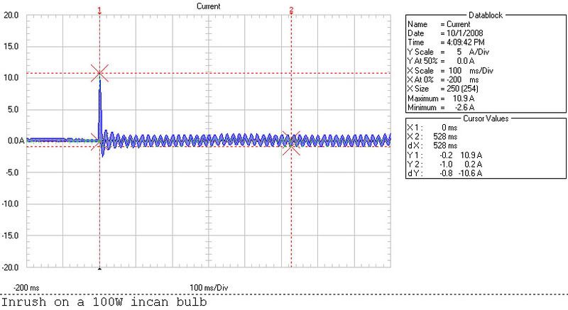
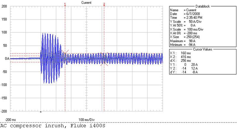
Here's a inrush capture of a 100W light bulb and then a A/C compressor. I did one on a 220V 4500W water heater but didn't save it. It was much like the light buld or even less. Not much if any inrush on a resistive load.

Light_C_1.jpg


Comp_Inrush_2.jpg
 
090205-1441 EST

philly:

Yes. That is why it is good to have someone other than the writer proofread what is written. I make all sorts of goofs like that. What is in the brain does not always end up correctly on paper, especially stuff typed on a computer.


winnie:

I think the contact rating problem has a lot to do with the arcing from an inductive load. This can occur both at turn on when contact bounce occurs, and at turn off when opening is intended. There is much higher inductance in the case of a motor load, therefore more energy, than there is inductance with a resistive load.

It is even a bigger problem on DC with an inductive load because of one way transfer of contact metal.

In the old days automotive breaker points lasted about 10,000 miles. Then Ford invented a means to reduce the problem. This was a hole in the center of one contact so the unidirectional metal flow was out thru the hole rather than on to the contact. I do not know how much this extended contact life. Probably mid 1950s.

I use a P&B KUP type relay for DC switching of a highly inductive clutch. These relays last about 3 to 6 months before the metal conical mound on one contact gets to be too large for reliable switching. This mound corresponds with a cavity in the other contact.

.
 
Here's a inrush capture of a 100W light bulb and then a A/C compressor. I did one on a 220V 4500W water heater but didn't save it. It was much like the light buld or even less. Not much if any inrush on a resistive load.

You mean duration of the inrush of the incandescent bulb is much smaller than the compressor. Otherwise the incandescent maximum inrush is 1:54 compared to the compressors 1:5. So incandescent inrush is much higher than motoric loads.
 
Status
Not open for further replies.
Top