
Bravepotato
Member
- Location
- Texas
Guys, after studying Mike's Motors, conductor sizing and voltage drop DVD's and book for the last 3 days almost 10 hours a day I am going back to test my newfound knowledge on Ray Holders cheap Practice exam test, which is what I studied for a week the first time I took the Masters last March (passed NEC general knowledge section, failed calculations by 3 points). I am doing MUCH better on these questions now. Mikes stuff is worth every penny.
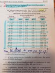
I cannot make sense of this question. I found my FLC in the 3 phase table, (74.8A), multiplied it by the obligatory 125% for continuous duty motors, (section 430.22) and then I multiplied that by the .75% I found in Table 310.15(B)(2)(a) for the given ambient temp rise of 50 degrees C (with 75 degree terminals) in the question, and came up with 70.12 amps. I realize that is a lesser amperage then what the 3 phase table shows, and definitely lesser than the 125% rule, and I realize if I sized my conductor by this number (70 amps) I would end up with a gauge that wouldn't support the startup of the motor.
However, I cannot for the life of me find where it tells you to "divide" the correction factor given in table 310. 15b2a....it clearly says "Multiply" (yellow highlighter). In the notes or otherwise.
Can anyone give some insight because Id like to know the correct procedure before I continue on with trying to answer these types of questions. Thanks!!

")