Help with a test

Status
Not open for further replies.

Dexie123

Senior Member
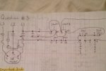
I need to wire a contactor 3 phase and implement two stop/start switches and a jog switch.

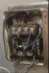
I cant tell how to wire this contactor (that I've enclosed the picture of). I can see L1, L2, and L3 and I don't have to worry about T1, T2, and T3 but I just have to have the have the control circuit pull in the contactor.

Any advice?
 

Attachments

  • Contactor.jpg
    Contactor.jpg
    8.1 KB · Views: 0
  • Motor control circuit.jpg
    Motor control circuit.jpg
    14 KB · Views: 0
If you understand your drawing, Don's link is mostly drawings and maybe even has nearly same thing you have in it someplace.

That doesn't tell you how to physically connect to the starter you have though, to be able to do that you need to understand the physical characteristics of the starter.

Something tells me you possibly understand the drawing but can't figure out how to make it physically work with the unit it represents.

The best way I can tell you to do that is to actually disassemble a few different units and pay attention to details of what you are looking at when you do so. There will be slight differences between one model and another, but they will all still have the base components, coil, armature, power contacts, aux contacts, overload assembly, overload contact(s).
 
Thanks for your comments guys.

Exactly Kwired. Based upon the picture of the contactor where would I find C1, C2, C3, and M? This contactor is old. Any idea where I can pick something like this contactor up?
Can you provide a higher resolution picture of the contactor? Hard to make out parts of the contactor, let alone the connections, with the picture provided.
 
Thanks for your comments guys.

Exactly Kwired. Based upon the picture of the contactor where would I find C1, C2, C3, and M? This contactor is old. Any idea where I can pick something like this contactor up?
You should be able, on close inspection, to see wires which are connected directly to the coil winding. That will be a good start. Once you identify the coil winding which is not connected to an L terminal you should be able to follow that through the two overload contacts to the control point.
Next try to identify the leads to the NO and NC auxiliary contacts.
I think that M represents the contactor coil itself.
 
Picture is not all that clear, but there are many similar looking starters from different manufacturers all around same age. The coil is about in the center of the whole thing, there should be two terminal screws in this vicinity and they are likely the coil terminals. Your actual C1,C2,C3 markings may be on a terminal elsewhere with a factor installed jumper to a common component.

The contacts "terminals" on these series of starters are typically on the top of the unit, usually the line side is considered the ones closer to the front of the unit as the load side usually has factory jumpers already installed to the overload assembly and is put at the rear where it wouldn't need field terminations attached very often. There is a fourth pole in the set of contacts but the fourth usually only has light duty contacts which you can't see unless you disassemble the unit, this is the aux contact for typical "holding circuit" control schemes, is typicaly labeled with a 2 and a 3, and term 3 is typically also factory jumpered to one side of the coil. (I believe this 2 and 3 is the same thing your drawing is calling C2 and C3. C1 is typically same power terminal as L1 and often is marked both L1 and 1.

Again understanding the base components is a must, as they can appear quite different from one contactor/starter to another and are not always arranged in same fashion.

Then enter the IEC contactors where a lot of the components are kind of not easily visible and you can get confused pretty easily, and they don't typically use same numbers on terminals as NEMA does either.
 
Status
Not open for further replies.
Top