Hey Mr. Faraday, explain this! (theory)

Status
Not open for further replies.

crossman

Senior Member
Location
Southeast Texas
Faraday's Law for voltage induced in a loop of wire is based on the rate of change of flux density within the loop. I had never looked at induced voltage from that perspective, I had been taught "flux cutting conductors".

Being inquisitive, I performed the following experiment:

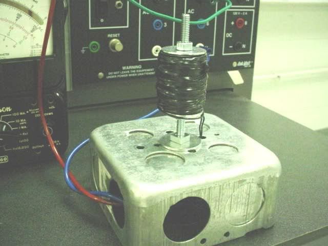
First, I built a primary out of a 1/2 rigid coupling, a long 1/4-20 bolts, a couple fender washers, and about 200 turns of #22 insulated wire. I wrapped the coil with electrical tape to hold the wire on. I mounted this on a 4-11/16 box.

a1primary3.jpg


Then I wound a secondary of about 4" diameter with about 200 turns of the #22 wire.

a1secondary.jpg


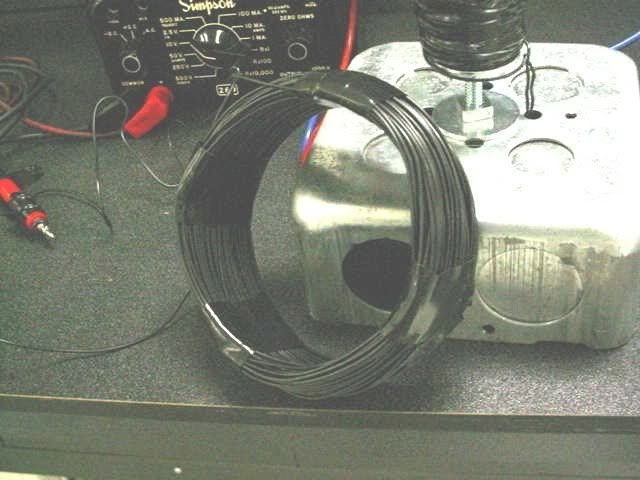
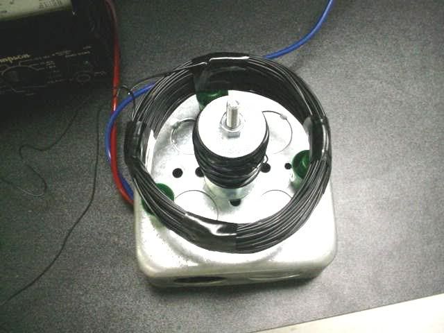
Next, I placed the secondary over the primary and supported it with plastic dry-erase marker caps.

a1xfmrabove.jpg


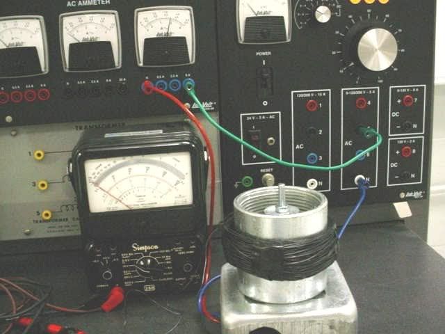
Then I connected a variable 60Hz AC source to the primary. I used a Simpson analog meter set on the 10 volt scale. I increased the primary voltage to a level that put 6 amps in the primary. The built-on panel ammeter read 6 amps. The Simpson read 2 volts on the secondary as evidenced in the photo below.

a1nocoupling.jpg


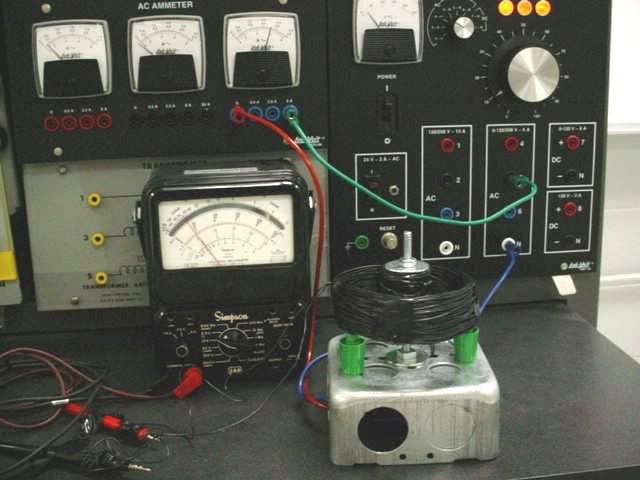
So far so good. But then I took a 2 1/2 inch rigid coupling and placed it between the primary windings and secondary windings. The current on the primary was still 6 amps. The voltage on the secondary fell to zero (or very close to zero as far as I could tell.) This is evidenced in the photo below.

a1coupling.jpg


Note that the photos are from the actual experiment. I did not cheat in any way. This really happens. Try it yourself.

Now what can we say about Faraday's Law concerning flux density in the loop? The same amount of current is flowing in the primary in both cases. Doesn't this imply the same flux density? What do you "flux density" guys have to say about this?

I'm pretty sure I know what is happening. Any thoughts?
 
If I have this right, the MMF is the product of turns x current so it will be constant but by adding the coupling you've changed the effective length of the magnetic circuit as well as the permeability so the flux density will change. The coupling also acts as a Faraday cage and routes the flux away from the secondary which causes the voltage to decrease.

Hopefully I got it right
 
Thanks for that reply. I understand your thoughts. I'm seeing it a little differently than you are, not that you are wrong. Let me add some comments:

Of course, the premise of my experiment is that 6 amps of 60 Hz current in the primary is going to cause the same amount of flux to be produced regardless of whether the steel coupling is in the loop or not. Yes, the steel coupling will cause alot of that flux to be inside it, but isn't all that flux in the coupling still inside the secondary loop?

Food for thought: Without the coupling, we are going to lose some flux to the outside of the secondary loop, decreasing the flux density on the inside of the loop. With the coupling, almost all of the flux will stay inside the secondary loop. Therefore, the flux density inside the secondary loop with the coupling in should be greater than without the coupling. And Faraday says that should cause a GREATER voltage, not a smaller one!

I am still pretty sure I know what is happening. Any other takers?
 
I am not a 'flux density' person, but a 'net flux enclosed by the loop'.

If you assume constant flux density over a given area, then the flux enclosed by the loop is simply the product of flux times area. So to the extent that flux density is constant, I am a flux density person. I'm also happy with integrating flux density over an area to claculate net flux.

But if the flux density is not constant, then you need to figure out some way to calculate the total flux enclosed by the loop.

With the transformer that you set up, the total flux enclosed by the secondary was equal to the flux flowing through the 'core' (the 1/4-20 bold) less any flux that returned via the air between the primary and the secondary. Imagine a plane defined by the secondary coil. At the center of this plane you have a steel core with flux flowing 'up' out of the plane (at a given moment in time), and everywhere else in the plane you have much lower flux density flowing _down_. Since flux always travels in loops, the amount of flux flowing 'down' through this plane must equal the flux flowing 'up'. The flux enclosed by the coil is the sum total of the flux flowing up inside the coil less the flux flowing down.

When you put the 2-1/2" coupling inside the secondary, you provided an improved path for the flux flowing down, but _inside_ your secondary. More of the flux through the core is balanced by flux returning, so that the _net_ flux enclosed by the secondary is greatly reduced.

If you remove the 2-1/2" coupling from inside the secondary, and add a larger coupling on the _outside_ of the secondary, then you will see the voltage go up.

-Jon
 
With the coupling in place, the outer loop is no longer being cut by lines of flux. They are trapped within the coupling. You have created a shield, not a means of coupling the magnetic fields associated with the two windings.

Take a look at the way many transformers are built. A ring of metal has the primary wound around one side and the secondary wound around the other side. The magnetic field generated by the primary current is transfered via the metal to the secondary windings. Such fields "travel" better through metal than through air. It is in this sense that the two windings are "coupled" by the metal core.

Your experiment does not couple the windings in the same sense. The primary is not wound around the metal, so the metal will not serve to carry the field to the secondary. That tends not to matter, because the secondary is not wound around the metal either.
 
You have proven how a faraday cage works.

This is why few US VFD applications have EMI/RFI problems when the circuits have been installed in grounded conduits.
 
Another way of expressing what Charlie said:

Your primary flux path goes through air to get from the top around to the bottom of the coil. In your initial experiment, a lot of the flux went outside the secondary coil so that there was a net flux inside the coil, inducing the measured voltage.

In your second experiment, you provided an easier path for the flux to get to the bottom of the primary coil by putting the steel coupler in the path. Now, practically all of the flux goes through the steel coupler so that the net flux inside the secondary coil is nearly zero (one direction in the bolt and the other direction in the steel coupler).
 
Your flux is in circles going through the center of your first coil, out, around, and back through the center. (Remermber, flux lines are always closed loops. Even if it loops out to infinity and back again.) Some of the flux lines return inside your second coil, and some return outside the outter coil.

When you insert the 2" coupling, almost all the flux lines return back around inside the coupling. So the "net" flux inside the coil is reduced to almost zero.

Steve
 
Woohoo!

Great explanations from everyone, and exactly what I had figured out myself.

Just to reiterate what y'all said:

From a "flux cutting conductor" perspective, the metal coupling acts as a shield, trapping the flux into the coupling and preventing the flux lines from cutting the secondary conductors.

From a "changing flux density in the loop" perspective, the flux lines in the primary core are going "up" while the flux in the coupling is going down, and they cancel out as far as flux density is concerned. Therefore, there is no changing flux density within the secondary loop.

So Mr. Faraday is still correct!:grin:

But it is very important to understand how to use the formula. The orientation of the loop to the primary field is important, but so is the method used to calculate the flux density. I hope my extended ramblings have been useful to someone.

Thanks guys.

P.S. I should have presented the experiment differently... instead of telling you the coupling-secondary-voltage was 0 volts, I should have asked y'all to guess what it was.
 
So, just curious here. Crossman, what would happen to the flux lines if a bar magnet was inserted in place of the 2" coupling? Say first with the North pole facing the j-box and then with the south pole facing it? :smile:
Forgive me for such a juvenile question if it's interpreted that way.
 
wbalsam1 said:
So, just curious here. Crossman, what would happen to the flux lines if a bar magnet was inserted in place of the 2" coupling? Say first with the North pole facing the j-box and then with the south pole facing it?

Hello there! Good question. Some additional info is desired. The coupling is a ring that goes completely around the primary. When you say "bar magnet" are you talking about some type of circular magnetic ring shaped exactly like the coupling except being magnetic with a north pole and south pole?

Or are you just talking about placing a rectangular bar magnet just on one side of the primary?

Calrify that and we can discuss it.

Some specualtion is as follows: Since the primary is AC 60 Hz sine wave current, a bar magnet is going to be alternately attracted to and repelled from the primary poles because they are constantly flipping north - south. I would have to snugly tie the bar magnet in place to keep it from moving I suspect.

Affect on the xfmr? I don't know right now. I kind of want to say that the steady magnetic field of the magnet would have no affect on the experiment, again because it is a steady field while the AC primary is sinusoidal. When the primary was at a polarity where the bar magnets field was canceling it, that part of the sine wave would cause a weaker secondary voltage, but then when the primary field changed polarity, the magnet would be aiding the field and causing a higher secondary voltage, so overall net effect is zero and the voltage is as before.

That's my quick-response guess. Sounds plausible that the permanent magnet would not affect the sinusoidal voltage produced. But I could be completely wrong.

Any other takers?
 
I would think that introducing a permanent magnet into an AC magnetic field would result in something similar to a DC offset imposed on an AC voltage wave.

If the DC is greater, you'd have a single polarity that varies in strength. If the AC is greater, you'd have an offset that spends more than 50% at one polarity.
 
Last edited:
It is my understanding

It is my understanding

That the magnetism is the function of an inverse square of distance. The closer you can make the secondary winding to the first will produce dramatic results.
 
LarryFine said:
I would think that introducing a permanent magnet into an AC magnetic field would result in something similar to a DC offset imposed on an AC voltage wave.

If the DC is greater, you'd have a single polarity that varies in strength. If the AC is greater, you'd have an offset that spends more than 50% at one polarity.

Larry, I can't say this for certain, but.... Assume the AC voltage to primary is turned off. Since the bar magnet is a steady field and not changing, if we simply place it near the secondary coil and let it just sit there without moving, it will have zero effect on the voltage induced in the coil.

Again, if the AC is off, and we we are putting the magnet into place between the pri and sec, there is relative motion between its magentic field and the secondary, so for a brief instance, you would notice a voltage change in the secondary, but as soon as the magnet stopped moving, we are back to zero volts in the secondary. The magnet no longer affects the voltage.

Now, turn on the AC to primary. The AC primary field will react with the permanent magnet field in an alternating way. But still, the only field that is changing is that from the primary. So I am thinking the magnet has no effect.

All specualtion of course...
 
quogueelectric said:
That the magnetism is the function of an inverse square of distance. The closer you can make the secondary winding to the first will produce dramatic results.

That is true and can be explained with either the "flux cutting conductors" view of induced voltage, or the "rate of change of flux density in loop" view.
 
yes

yes

crossman said:
That is true and can be explained with either the "flux cutting conductors" view of induced voltage, or the "rate of change of flux density in loop" view.
You took the words right out of my mouth!
 
crossman said:
Hello there! Good question. Some additional info is desired. The coupling is a ring that goes completely around the primary. When you say "bar magnet" are you talking about some type of circular magnetic ring shaped exactly like the coupling except being magnetic with a north pole and south pole?

Or are you just talking about placing a rectangular bar magnet just on one side of the primary?

Calrify that and we can discuss it. .....

I was at first thinking of a bar magnet facing vertically down into the space between the two coils, but I am more interested now in hearing your discussion on a circular magnet laying horizontally interposed between the two coils. Thanks for your interest in the question. :smile:
 
crossman said:
Now, turn on the AC to primary. The AC primary field will react with the permanent magnet field in an alternating way. But still, the only field that is changing is that from the primary. So I am thinking the magnet has no effect.
I think you are right. Unless the magnet moves, there is no changing flux from the constant magnetic field.

One thing you will find, however, is that after your experiment, you will no longer have nearly as strong a permanent magnet. The AC coil scrambles up the atomic structure to remove the magnetism. All you would be left with is some residual magnetism from the final flux when the AC is turned off. This is the principal used in degaussing a television screen.
 
To analyze the circular magnet use the magnetic circuits approach. It works the same way as Ohm's law, just with magnetism. The primary is a source of magnetomotive force (MMF) coming from one end, and that MMF needs to find a route to the other end - think battery. The MMF induces some magnetic flux to travel some route through some reluctance to get to the other end of the primary. Reluctance works the same way as parallel resistors, just using proportional areas multiplied by the permeability of those areas times path length.

Some relative permeabilities:
Vacuum: 1
Air, most other gasses, nonferrous metals, plastics: 1.00001 or so
Typical steel: 800-1000
Soft ferrite: 2000-5000
Machine steel, used in motors and transformers: 2000-6000
There are some other very expensive materials that can reach 10,000-30,000 or more

Using the magnetic circuits approach, the only difference between a circular magnet and a rigid coupling is the dimensions and the relative permeability. If the magnet is the same diameter, wall thickness, and height as the coupling we could expect a similar result in the experiment. The only difference would be the magnet's higher permeability (ferrite vs. steel) so the meter that read zero before would read even closer to zero now - we would need a more precise setup to see anything useful.

Jeremy
 
I played around with the magnet and the xfmr earlier.

First, I took just the primary with 6 amps through it, held a ceramic bar magnet in my fingers and slowly moved it towards the coil. At about 3 inches, I could feel the magnet vibrating. The closer I got, the more it vibrated. This was actually expected, but was none-the-less pretty darned cool. I could also here the 60Hz hum as the magnet got close. If I put the magnet against any of the steel parts, it would still stick, but it was definitely humming.

Also, as the magnet got closer, the amperage went down slightly, from 6 amps to a minimum of 5.7 amps with the magnet held against the primary windings.

Next, I removed the magnet and I put the secondary winding over the primary, just like in the actual experiment from the first post in this thread. Primary was set at 6 amps, voltage induced in secondary was 2 volts. The I slowly placed the bar magnet in between the primary and secondary. The voltage slowly decreased as the magnet went further in. It decreased down to 1.75 volts, not a lot of difference from 2 volts, but still significant. Now, the bar magnet had way less area than the 2-1/2" rigid coupling.

Sounds to me like the bar magnet simply blocked some of the flux that could cut the secondary. This seems to agree with what jdsmith wrote above.

Another note for jghrist: The ceramic magnet seems just as strong now as it did before. I agree that a steel magnet could have its magnetism weakened by the AC field. Perhaps the molecular arrangement of the ceramic magnet is more firmly locked in place?

Edit: Additional thoughts
 
Last edited:
Status
Not open for further replies.
Top