crossman
Senior Member
- Location
- Southeast Texas
Faraday's Law for voltage induced in a loop of wire is based on the rate of change of flux density within the loop. I had never looked at induced voltage from that perspective, I had been taught "flux cutting conductors".
Being inquisitive, I performed the following experiment:
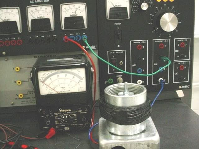
First, I built a primary out of a 1/2 rigid coupling, a long 1/4-20 bolts, a couple fender washers, and about 200 turns of #22 insulated wire. I wrapped the coil with electrical tape to hold the wire on. I mounted this on a 4-11/16 box.
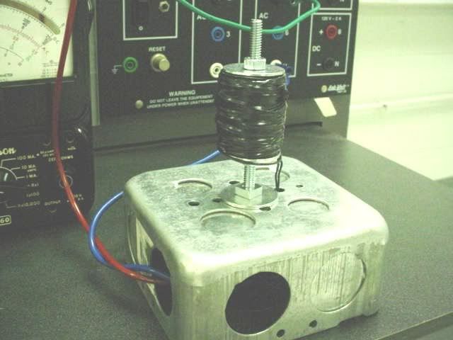
Then I wound a secondary of about 4" diameter with about 200 turns of the #22 wire.
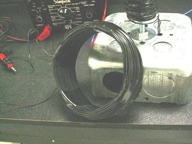
Next, I placed the secondary over the primary and supported it with plastic dry-erase marker caps.
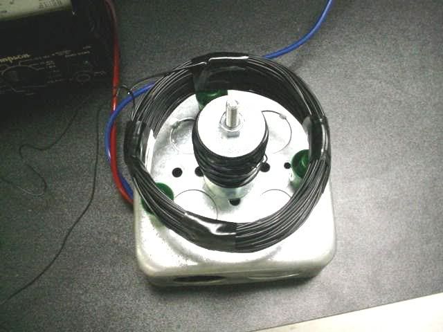
Then I connected a variable 60Hz AC source to the primary. I used a Simpson analog meter set on the 10 volt scale. I increased the primary voltage to a level that put 6 amps in the primary. The built-on panel ammeter read 6 amps. The Simpson read 2 volts on the secondary as evidenced in the photo below.
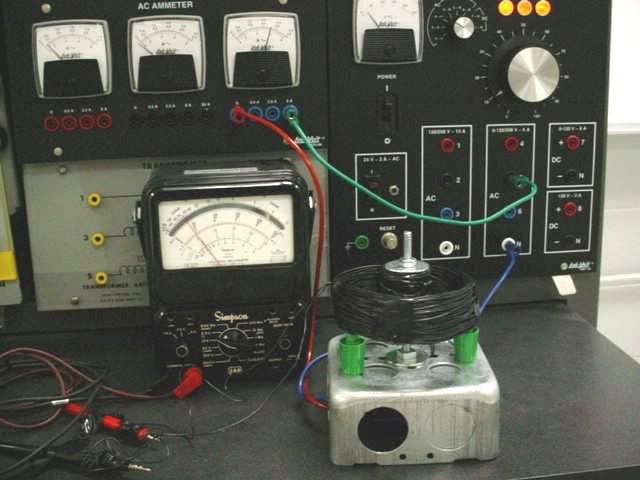
So far so good. But then I took a 2 1/2 inch rigid coupling and placed it between the primary windings and secondary windings. The current on the primary was still 6 amps. The voltage on the secondary fell to zero (or very close to zero as far as I could tell.) This is evidenced in the photo below.
Note that the photos are from the actual experiment. I did not cheat in any way. This really happens. Try it yourself.
Now what can we say about Faraday's Law concerning flux density in the loop? The same amount of current is flowing in the primary in both cases. Doesn't this imply the same flux density? What do you "flux density" guys have to say about this?
I'm pretty sure I know what is happening. Any thoughts?
Being inquisitive, I performed the following experiment:
First, I built a primary out of a 1/2 rigid coupling, a long 1/4-20 bolts, a couple fender washers, and about 200 turns of #22 insulated wire. I wrapped the coil with electrical tape to hold the wire on. I mounted this on a 4-11/16 box.

Then I wound a secondary of about 4" diameter with about 200 turns of the #22 wire.

Next, I placed the secondary over the primary and supported it with plastic dry-erase marker caps.

Then I connected a variable 60Hz AC source to the primary. I used a Simpson analog meter set on the 10 volt scale. I increased the primary voltage to a level that put 6 amps in the primary. The built-on panel ammeter read 6 amps. The Simpson read 2 volts on the secondary as evidenced in the photo below.

So far so good. But then I took a 2 1/2 inch rigid coupling and placed it between the primary windings and secondary windings. The current on the primary was still 6 amps. The voltage on the secondary fell to zero (or very close to zero as far as I could tell.) This is evidenced in the photo below.

Note that the photos are from the actual experiment. I did not cheat in any way. This really happens. Try it yourself.
Now what can we say about Faraday's Law concerning flux density in the loop? The same amount of current is flowing in the primary in both cases. Doesn't this imply the same flux density? What do you "flux density" guys have to say about this?
I'm pretty sure I know what is happening. Any thoughts?
