Hi-leg Delta xfmr reference?

Status
Not open for further replies.
Not really:

Not really:

mivey said:
I see what you are saying (I think). We are not following these phasors through time. We are looking at the phasors at a point in time. A photograph of a rotating phasor is what you are calling a static phasor.

Is that it?

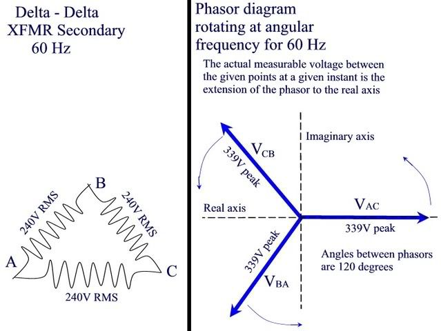
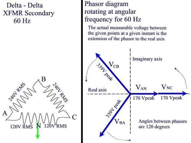
It is sorta like that. Freezing a rotating phasor at time zero would capture the phase angle, but the magnitude would be Vpeak.

The magnitude of a fixed phasor would be Vrms. This is what we use in stead-state analysis. Some extend the defintions to impedances.
 
Vrms or Vmax

Vrms or Vmax

rattus said:
Freezing a rotating phasor at time zero would capture the phase angle, but the magnitude would be Vpeak.

The magnitude of a fixed phasor would be Vrms.

I think the magnitude of the rotating can be shown either with Vmax or Vrms. It is just a transform of the time function. The time function can be shown with Sqrt(2)*Vrms or Vmax. It does not matter as long as you know the terminology being used. I think the same can be said for the "fixed phasor". We normally use the RMS value but are not restricted to that.
 
Nuh-uh:

Nuh-uh:

mivey said:
I think the magnitude of the rotating can be shown either with Vmax or Vrms. It is just a transform of the time function. The time function can be shown with Sqrt(2)*Vrms or Vmax. It does not matter as long as you know the terminology being used. I think the same can be said for the "fixed phasor". We normally use the RMS value but are not restricted to that.

For the rotating phasor, peak values are required in order for the instanteous values to be correct.

For the fixed phasor rms values are required in order to use them with impedances in steady state analyses.

They cannot be interchanged.

It is cleaner to leave out any multipliers.
 
phasor diagram or circuit diagram

phasor diagram or circuit diagram

rattus said:
It is sorta like that.

It would help me understand where you are coming from if you clarified the static phasor term.

This may sound like a leading questions but I'm not trying for entrapment. While that may be fun when butting heads with someone, it aggravates a situation where you are trying to understand what is being said.

I'll explain where I'm coming from so maybe you can help me understand your frame of mind.

I currently see two ways to see a static phasor.

If you are referring to a static phasor as a photograph of a rotating phasor, I'm in the same frame of mind.

If you are using the term static phasor to draw the voltage vector from a to b to c, I think this is where we differ. This is where I consider that you may be blending a phasor diagram with a circuit diagram. I don't think the term vector is outdated but I do think the term rotating vector is outdated.

I'm perfectly happy with either frame of reference. I have no problem stepping over to your frame of reference or using your terminology, I just like to know where I'm stepping so I can avoid toes, etc. :grin:
 
No multipliers

No multipliers

rattus said:
For the rotating phasor, peak values are required in order for the instanteous values to be correct.

For the fixed phasor rms values are required in order to use them with impedances in steady state analyses.

They cannot be interchanged.

It is cleaner to leave out any multipliers.

I have no problem with that.
 
Okay... this is my thought on what the rotating phasor diagram for voltages for a 240 volt RMS delta secondary should look like. Am I messing something up? Right now, it makes complete sense to me. (until someone tells me it is all wrong:mad: )

deltanoneutral.jpg
 
Henry Higgins

Henry Higgins

crossman said:
Okay... this is my thought on what the rotating phasor diagram for voltages for a 240 volt RMS delta secondary should look like. Am I messing something up? Right now, it makes complete sense to me. (until someone tells me it is all wrong:mad: )

deltanoneutral.jpg

By George, I think he's got it.
 
Drawings

Drawings

What are you using to draw this? You have made some very nice drawings here and elsewhere.
 
Rms

Rms

Also, you could show the RMS value on the diagram, as long as everyone understands what you are doing. More often than not, that is what is done.

You hardly ever see people drawing a 170 volt phasor. It is usually the 120 volt RMS value you see.
 
convention. again.

convention. again.

mivey said:
You hardly ever see people drawing a 170 volt phasor. It is usually the 120 volt RMS value you see.

BTW, rattus does not seem to like that convention so take note: you may have to communicate with him one way and most everybody else another.
 
mivey said:
What are you using to draw this? You have made some very nice drawings here and elsewhere.

MicroSoft Photodraw - photo editor with drwing tools. You can do the same thing with the Paint program that comes with windows, only it is a tad more difficult to work with.
 
mivey said:
Also, you could show the RMS value on the diagram, as long as everyone understands what you are doing. More often than not, that is what is done.

You hardly ever see people drawing a 170 volt phasor. It is usually the 120 volt RMS value you see.

I have seen the diagram indicating Vpeak instead of the actual 170 volts or 339 volts as I have shown. One thing I don't understand... if we use the RMS values in a rotating phasor diagram, then as the phaosr rotates, the projections onto the real axis cannot be the real and correct voltages at various points in time. I would think that a RMS phasor would be a static vector, and not rotating. I would like to better understand the application of the RMS phasor. You can't really rotate it and get any meaningful results without applying a multiplier as rattus has indicated?
 
On the other hand, if we indicate 120 volts RMS, then for a sine wave voltage, this leads to 170 volts peak, so as long as we use the peak, we can label the phasor 120 v rms. The magnitude in actuality is still Vpeak?
 
crossman said:
I have seen the diagram indicating Vpeak instead of the actual 170 volts or 339 volts as I have shown. One thing I don't understand... if we use the RMS values in a rotating phasor diagram, then as the phaosr rotates, the projections onto the real axis cannot be the real and correct voltages at various points in time. I would think that a RMS phasor would be a static vector, and not rotating. I would like to better understand the application of the RMS phasor. You can't really rotate it and get any meaningful results without applying a multiplier as rattus has indicated?

The phasor is a transformation of the time function. The idea is to get away from the math that goes along with time.

If you want to deal with time, use v(t) = sqrt(2)*V_rms*COS(wt+phi) or v(t) = V_max*COS(wt+phi) or v(t) = V_max*(e^jphi)*e^jwt or v(t) = sqrt(2)*V_rms*(e^jphi)*e^jwt as they are all the same.

crossman said:
On the other hand, if we indicate 120 volts RMS, then for a sine wave voltage, this leads to 170 volts peak, so as long as we use the peak, we can label the phasor 120 v rms. The magnitude in actuality is still Vpeak?

Correct. Most of what we are going to see here is the RMS value. I usually don't see a "label of RMS" but that would be the clearest way to do it. Shorthand can lead to a misunderstanding. Most books start out with a "conventions used" section, then use the shorthand.

Most people know 120 is RMS. If you had a phasor with the label "120@0" most would know this is rms. If you put "170@0", I bet most would do a double-take.

[edit: typo]
 
Last edited:
magnitude

magnitude

crossman said:
On the other hand, if we indicate 120 volts RMS, then for a sine wave voltage, this leads to 170 volts peak, so as long as we use the peak, we can label the phasor 120 v rms. The magnitude in actuality is still Vpeak?

To nit-pick: The magnitude of Vrms is the positive value of Vrms. The magnitude of Vpeak is the positive value of Vpeak. The maximum value of the wave represented using the Vrms notation is Vpeak.
 
Now, say we have a high-leg delta system. Would it be proper to show the voltage phasor from A to C as being split by the Neutral as in the following diagram?

deltaneutral.jpg
 
crossman said:
Now, say we have a high-leg delta system. Would it be proper to show the voltage phasor from A to C as being split by the Neutral as in the following diagram?

deltaneutral.jpg

First off, you are showing a wye diagram. Connect all the arrows head to tail to form an equilateral triangle.

Second, these are static phasors and their magnitude is 120Vrms. It is confusing to provide peak values.

Yes, the head to tail connection of the 120V phasors is correct, but it is not the only correct configuration.
 
Last edited:
don't confuse circuit and phasor diagrams

don't confuse circuit and phasor diagrams

As for the phasor diagram, an open-type phasor diagram is the preferred method. Also, don't get confused and mix a phasor diagram with a circuit diagram. They are not the same thing.

A closed-type phasor diagram may LOOK like the circuit diagram but a circuit diagram and phasor diagram serve two different functions.

Most protective relay manufacturers use the standard that the arrows and subscripts are the actual or assumed direction of current flow during the positive half-cycle of the ac wave. A notation of Vab would have an voltage arrow pointing from b to a and a current arrow pointing from a to b and indicates a voltage drop from a to b.

A circuit diagram uses these notations when showing the location and assumed directions of current and voltage drops. A phasor diagram shows the current and voltage magnitudes and phase relations.

For a delta circuit, think about the difference in what you would see in the closed type phasor diagram and what would appear on the delta circuit diagram. For example, lets consider a phasor diagram with a on the x-axis, b oriented 120 degrees clockwise, and c oriented 120 degrees counter-clockwise. Use this same a-b-c layout for the delta circuit. The arrow on the phasor diagram would be pointing from b to a and would be labeled Vab. On the ciruit diagram, this would be a voltage drop from a to b and the arrow would be reversed. You can see the same can be said for the phase to neutral arrows.

The open-type phasor diagram avoids this confusion and that is why it is the preferred method

crossman, you could probably draw a nice picture of this.
 
[edit: IGNORE THIS POST. I MESSED UP THE QUOTE COPY]

rattus said:
First off, you are showing a wye diagram. Connect all the arrows head to tail to form an equilateral triangle.

Second, these are static phasors and their magnitude is 120Vrms. It is confusing to provide peak values.

Yes, the head to tail connection of the 120V phasors is correct, but it is not the only correct configuration.

This is not correct. Now that you have the concept of phasors down, let's work on the notation a little bit.

I'll have to look at the labels but as far as the location of the VNC phasor, it would be located directly on top of the VAN phasor. Read my other post and let me know if this is not clear.

[edit: IGNORE THIS POST. I MESSED UP THE QUOTE COPY]
 
Last edited:
Status
Not open for further replies.
Top