Home still getting surges after driving deeper ground rods. Is there a grounding issue at the pole?

GroundGuy

Member
Location
Florida
Occupation
IT
Please correct me if I'm wrong, isn't the metal spacer on that split bolt connector in the wrong place? You don't want dissimilar metals directly touching (copper to aluminum or copper to steel) as this can cause electrolysis. In the pic, it should be bare copper, spacer, then the fiber bond.
FYI, copper to steel or iron connections (especially welded) are a thermocouple and create voltage based on temperature.
Yes the spacer is typcially used when there are dissimilar metals. Is that the jacket stainless steel?

Also copper and steel can touch each other. We screw copper pigtails to metal boxes all of the time.
The jacket might be aluminum. It's not specified in the product description and I have a (weak) magnet that didn't seem to be sticking.
I'll get the spacer put between them. Thanks guys!
 

LarryFine

Master Electrician Electric Contractor Richmond VA
Location
Henrico County, VA
Occupation
Electrical Contractor
Please correct me if I'm wrong, isn't the metal spacer on that split bolt connector in the wrong place? You don't want dissimilar metals directly touching (copper to aluminum or copper to steel) as this can cause electrolysis. In the pic, it should be bare copper, spacer, then the fiber bond.
You are correct, of course. I put them between the wires even when they're the same type.
 

kwired

Electron manager
Location
NE Nebraska
The jacket might be aluminum. It's not specified in the product description and I have a (weak) magnet that didn't seem to be sticking.
I'll get the spacer put between them. Thanks guys!
Magnet wouldn't stick to certain grades of stainless either. try gouging it with a sharp object, if it is really soft it is likely aluminum. If pretty hard it is probably stainless.

If this "shield" ends outside your home I really doubt it is much of a factor to your problems if it is a fiber cable. The fiber isn't going to carry any surge into (or out of) the building unlike copper pairs or a coax cable might be able to do.
 

Hv&Lv

Senior Member
Location
-
Occupation
Engineer/Technician
The problem is I'm still losing electronics to surges.
The surge protectors' LEDs still indicate they are providing protection.

I'm contacting FPL to check that the grounding and lightning arrester at the pole are not compromised, as they have numerous ground runs and bonding going on at the top of the pole.


In the last picture it appears the overhead neutral is coupled to my neutral service wire and to the ground wire on the pole.
The neutral is hooked up to my meter.
The neutral and ground are tied at my main service panel. There are untied in my subpanel.
you didn’t take a picture of the front of the transformer. Those XF bars are crap and can come loose.
surge when no lightning storm happening?? Could be a neutral connection issue as mentioned earlier.
 

GroundGuy

Member
Location
Florida
Occupation
IT
you didn’t take a picture of the front of the transformer. Those XF bars are crap and can come loose.
surge when no lightning storm happening?? Could be a neutral connection issue as mentioned earlier.
Surges are only happening during lightning storms. Here's some pics of the front, neutral looks connected.

038d274ac7.JPG

393c3de39a.JPG

14473b9f90.JPG
 

GroundGuy

Member
Location
Florida
Occupation
IT
Second, you only show having a Type 2 surge and reference a Type 3 at the critical equipment. While good under normal conditions (utility transient surges) Lightning surges enter a whole other level. Getting Type 1 to start would help. Each SPD is only capable of reducing just so much of the surge allowing some to still pass. Most will aim to just get rid of enough that only the worst event will possibly get by, due to costs/benefit ratio.

Very critical components can be benefited by starting with a Type 1 at your service then a Type 2 at the distribution panels. Another Type 2 branch circuit SPD and finally an equipment Type 3 SPD at point of use. Getting and stacking SPDs that are designed and listed to work together can enhance overall protection.
The only Type 1 SPDs I can find have about 1/3 the surge current rating of my Type 2 SPD (140kA).
Not sure if this really matters since it protects a different waveform than Type 2.

Type 1 36kA
Leviton R2120-B | Maximum Surge Current Per Phase: 36kA | VPR L-N : 700V | VPR L-L : 1200V | MCOV: 180V - $50
Siemens FSPD036 | Maximum Surge Current Per Phase: 36kA | VPR L-N : 700V | VPR L-L : 1200V | MCOV: 150V - $42

Type 1 50kA - 65kA
Type 1 with a bit higher surge current are the Leviton P and Siemens BoltShield (I accidentally called it Type 2 in my previous reply):
Leviton P2120-B | Maximum Surge Current Per Phase: 50kA | VPR L-N : 700V | VPR L-L : 1200V | MCOV: 180V - $266
Siemens QSPD2A065P | Maximum Surge Current Per Phase: 65kA | VPR L-N : 600V | VPR L-L : 1000V | MCOV: 150V - $130

And then I found the Type 2 with event counter that has significantly more current capacity but with a price to match:
Leviton X2120-020-00C | Maximum Surge Current Per Phase: 400kA | VPR L-N : 700V | VPR L-L : 900V | MCOV: 175V - $2000

From this selection, the Siemens BoltShield QSPD2A065P looks like the best specs. Since I already have this one on my subpanel, I could move it to my main panel to have it alongside my Type 2, and get another Type 2 for my subpanel to replace it.
 

GroundGuy

Member
Location
Florida
Occupation
IT
I have some time on my minds so I picked up a Extech 382252 Earth Ground Resistance Tester Kit to do the Fall of Potential test on my POCO pole's ground and my home's ground system.

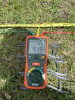
I did the 62% method with the farthest probe at 68 ft, which puts the center probe at 42 ft. All in a straight line. I zeroed the meter beforehand and also measured 0 earth voltage when the probes were placed.

For obvious reasons the earth ground at the POCO pole was still hooked up, which I know it is recommended to lift the ground during measuring.
The probes were 185 ft away from the next power pole that the pole I was measuring was hooked up to, so not sure how much it affects the reading to have the ground hooked up using this method.

I did lift the earth ground on my home when measuring, and made sure to flip the main disconnect off beforehand.
I didn't test each ground rod or the UFER ground individually since I didn't want to dig up pavers and disconnect them.
I suspect the 90 deg reading is higher than the 45 deg one due to being a bit closer to the UFER foundation or just soil conditions.
But overall it looks like the ground resistances all check out and are well below the NEC's <25 Ω requirement.

POCO Pole Earth Ground
59% = 3.89 Ω
62% = 4.19 Ω
65% = 4.66 Ω

Home's Earth Ground (2x 20ft ground rods + foundation UFER)
Location 1: (45 deg to foundation)
59% = 5.69 Ω
62% = 5.98 Ω
65% = 7.11 Ω

Location 2: (90 deg to foundation)
59% = 7.73 Ω
62% = 8.34 Ω
65% = 9.14 Ω


SPD Type Explanation
In the beginning of this thread it was recommended to get a Type 1 SPD as only having a Type 2 wouldn't provide as much lightning surge protection on the main service panel.
This is a misconception. I did talk with Siemens and they informed me that the UL certification only tests for 8/20 µs waveform. They don't test for 10/350 µs waveform like the IEC certification. This is the same for other SPD companies as well in the US who only certify for UL.
The ONLY difference between Type 1 and Type 2 in the UL certification is were it is allowed to be installed and if it requires an overcurrent protective device, not what type of waveform it protects against.
A type 1 or a Type 2 will perform the same if installed in a meter load center combo panel.

UL
Type 1 — One port, permanently connected SPDs, except for watt-hour meter socket enclosures, intended for installation between the secondary of the service transformer and the line side of the service equipment overcurrent device, as well as
the load side
, including watt-hour meter socket enclosures and Molded Case SPDs intended to be installed without an external overcurrent protective device.
Type 2 — Permanently connected SPDs intended for installation on the load side of the service equipment overcurrent device; including SPDs located at the branch panel and Molded Case SPDs.
Type 3 — Point of utilization SPDs, installed at a minimum conductor length of 10 meters (30 feet) from the electrical service panel to the point of utilization, for example cord connected, direct plug-in, receptacle type and SPDs installed at the utilization equipment being protected. See marking in 80.3. The distance (10 meters) is exclusive of conductors provided with or used to attach SPDs.
 

Attachments

  • signal-2024-07-28-184802_002.jpeg
    signal-2024-07-28-184802_002.jpeg
    565.7 KB · Views: 7
  • signal-2024-07-28-184802_003.jpeg
    signal-2024-07-28-184802_003.jpeg
    329.5 KB · Views: 7
Last edited:
Top