080602-2050 EST
AKwiring:
A voltage source is a two terminal device that has a voltage difference between the terminals. I will include 0 V within this definition. The maximum voltage is any reasonable value.
For an ideal voltage source the voltage at its terminals will remain constant independent of load. In real life virtually all sources have an internal impedance that means under load that the terminal voltage usually drops with increasing load. However, there are some regulated supplies that have an extremely low internal impedance. Also some inductive and/or capacitive loads might cause higher terminal voltages. For theoretical purposes we can assume ideal voltage sources.
Neither terminal of a voltage source needs to be connected to a chassis, neutral, common, earth or any other voltage or current source. However, one terminal can be connected to any one or in some cases more than one of these.
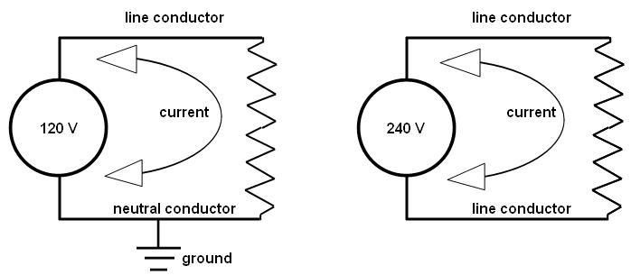
In a common United States electrical distribution system to a residence you have two 120 V 60 Hz AC voltage sources connected together at a transformer center tap. Because the transformer is wired to add the two voltage sources together you have three possible ways to connect to the secondary.
1. Connect between the center tap and one outside lead of the secondary. This provides a nominal 120 V output with a phase of 0 (arbitrary choice) on the hot lead relative to the primary. I will call the center tap common. But below I will call one of the outside leads common.
2. Connect between the center tap and the other outside lead of the secondary. This provides a nominal 120 V output with a phase of 180 deg on this other hot lead relative to the primary (based upon the above arbitrary choice of 0 for connection 1).
Note: I have not connected any of the secondary leads to anything except my measuring instruments. To show phase relationships I would probably use an oscilloscope.
Quite often on transformer schematic diagrams a dot will be placed adjacent to a lead to indicate its phase relationship to other leads.
3. Make the second outside lead common (a reference point) and the first hot lead of item 1 the hot lead. Now the voltage is 240 V and of phase 0.
If the center tap did not exist as a terminal or I did not use the center tap, then I would call the combination of the two secondaries a single voltage source. It is really a matter of how you will use the device and how you want to analyze the circuit.
For some applications none of these leads would be connected to earth. However, in the conventional residential application the center tap will be called neutral and will be tied to earth. This earth grounding will at least be required at the main service entrance.
With this connection of the center tap to earth we have available in the home, under normal conditions, a voltage that does not exceed 120 V relative to any grounded surface. But we also have available 240 V between the two hot leads, neither of which is grounded, to use for higher wattage devices like stoves.
Note: when I say no voltage is greater than 120 V I am referring to the RMS voltage. The peak voltage of a 120 V RMS source is 1.414*120 = 170 V.
.


