How do I fix this?

Status
Not open for further replies.

iwire

Moderator
Staff member
Location
Massachusetts
I have been tasked with fixing a vertical conveyor system. The customer noticed that the LED indicators on one of the photo switches where out. They requested we replace it, we got the same model and it was a plug in replacement, I put in place, got the aim right and it seemed to work until the first bin went by a photo-switch beyond the one I changed.

Heres the thing though, I can't find any documentation or manufacturers name on the control panel. Further more it is controlled by a PLC without any means of accessing it.

What would you guys do?

Here is the inside

IMG_20161219_111120577_zpsereflh8f.jpg


And the cover

IMG_20161219_111153963_zpsiyihstyt.jpg


From left to right

Stop, Cycle start, waiting to unload, jog forward, jog reverse, fault reset, load fault, unload fault, over torque.

The photo-switch I am working with seems to be part of the unload fault programing.

Where would you start?
 
If the next photo swtich in line is the same, maybe try changing it out with the new one and put the "non working" switch back?
 
You said the replacement was a plug in replacement? So you may have not shut power off to change it?

I would cycle power to the entire PLC cabinet first and give it a solid minute before powering it back up again. You may have left the program in a random state when it was removed if you did it under power.

If it was powered down for the replacement, then I'd move on to verifying your photoeye is making/breaking it's contact when a bin is in front of it. When you know that is working, have someone stand in front of the plc while someone puts and takes a way that bin in front of the photoeye. You want to verify one of the input lights blinks on and off as the bin is inserted and removed in front of the eye.

If this all checks out and it still doesn't run correctly, you're going to need to track down a programmer.
 
My thought would be you would need to get out the laptop and plug into the plc to see the program in detail, but with no means to access you might have to rely on a good operator who knows the process.


Sent from my iPhone using Tapatalk
 
You said the replacement was a plug in replacement? So you may have not shut power off to change it?

I would cycle power to the entire PLC cabinet first and give it a solid minute before powering it back up again. You may have left the program in a random state when it was removed if you did it under power.

If it was powered down for the replacement, then I'd move on to verifying your photoeye is making/breaking it's contact when a bin is in front of it. When you know that is working, have someone stand in front of the plc while someone puts and takes a way that bin in front of the photoeye. You want to verify one of the input lights blinks on and off as the bin is inserted and removed in front of the eye.

In one way or another I have pretty much done all that with the one I changed.

If this all checks out and it still doesn't run correctly, you're going to need to track down a programmer.

I think so too, this post is a desperation move. You never know if someone on these boards has an answer.

This is in a store, no one on site has any info or knowledge about it.


Thanks for the response.
 
My thought would be you would need to get out the laptop and plug into the plc to see the program in detail, but with no means to access you might have to rely on a good operator who knows the process.

I have very little PLC experience and none with AB.

The 'operators' are all unskilled temp help, this is not in an industrial location it is in a store.

Thank you for the response.
 
161222-0911 EST

iwire:

Need more information.

1. Find out who made the machine and where are the logic diagrams.

With nothing else to go on, and I had to live with just the machine as is, then:

1. I would bench test the removed photo-detector and see how it works. This includes testing at at 90 V and 135 V. Figuring out the logic of the photo-detector itself. How are the dip switches set and does the removed detector function sequentially like it should. Is this a two terminal device, or does it have a separate power source from the switched circuit?

2. From someone that normally runs the conveyor I would try to determine the logical operation of the whole conveyor, and how the photo-detectors fit into the operation.

3. Is a single PLC input the only place that a single photo-detector is connected?

4. Suppose that the photo-detector has a separate power source from its switched circuit, then is that power always present? If not study that area. If power is always present, then at that photo-detector the output switch of the detector should always respond as expected for whatever is its internal logical setup. Does it at the detector?

5. If the photo-detector derives power from the series circuit that it switches (in other words a two terminal photo-detector), then try to trace that circuit and see what else might be in the path.

We need more information on what you can trace.

.
 
Need more information.

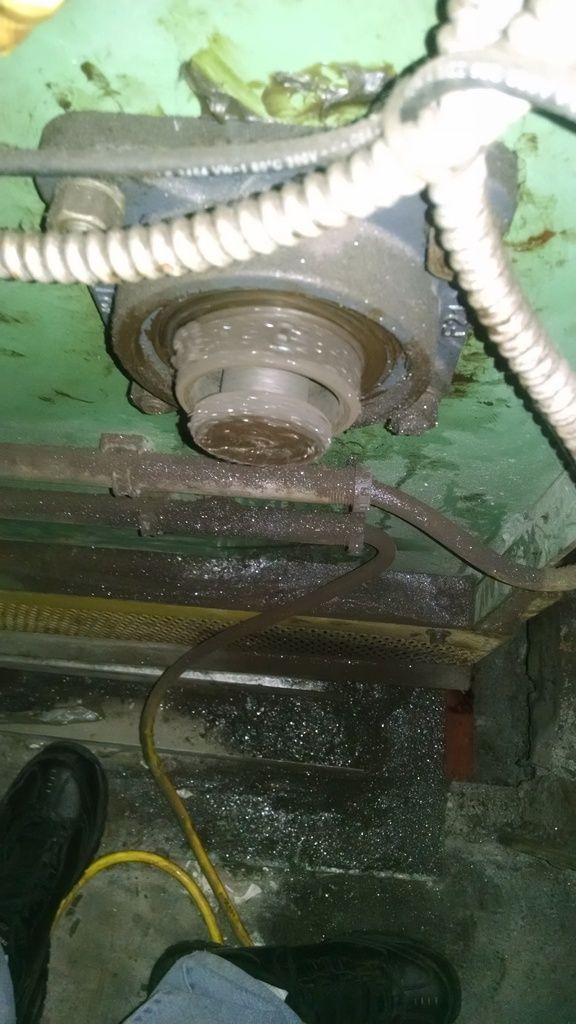
i can tell you the conveyor is green, :) that is about as much more info as I can provide.

I do agree with you about needing more information but this is why I am on the forum asking for suggestions.

1. Find out who made the machine and where are the logic diagrams.

I have tried to find any information, I cannot locate any manufactures name, the people on site do not know of any manuals, wiring diagrams or programing info.


With nothing else to go on, and I had to live with just the machine as is, then:

1. I would bench test the removed photo-detector and see how it works. This includes testing at at 90 V and 135 V. Figuring out the logic of the photo-detector itself. How are the dip switches set and does the removed detector function sequentially like it should. Is this a two terminal device, or does it have a separate power source from the switched circuit?

There are no dip switches, there is pot and it was set the same as the removed one. I am not seeing need to bench test the one I changed, when it changes state the you can see the PLC input change as well.

2. From someone that normally runs the conveyor I would try to determine the logical operation of the whole conveyor, and how the photo-detectors fit into the operation.

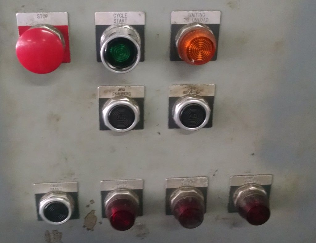
I agree this is what I need to know. However no one on site can help with that. They only know how to push the stop and start button. No qualified people for miles.


3. Is a single PLC input the only place that a single photo-detector is connected?

Good question, I can't answer that now but that is someting I could find that out.


4. Suppose that the photo-detector has a separate power source from its switched circuit, then is that power always present? If not study that area. If power is always present, then at that photo-detector the output switch of the detector should always respond as expected for whatever is its internal logical setup. Does it at the detector?

The photo-switch is always powered and seems to change state properly when a bin passes it

5. If the photo-detector derives power from the series circuit that it switches (in other words a two terminal photo-detector), then try to trace that circuit and see what else might be in the path.

No, the contacts might be in series with something but the power supply is not.

We need more information on what you can trace.

I can trace all the wiring, luckily this is a fairly compact unit.

There is a short horizontal conveyor on floor two that feeds the bins into the vertical conveyor, at the ground floor the bins are pushed out of the vertical conveyor onto another horizontal convenor.

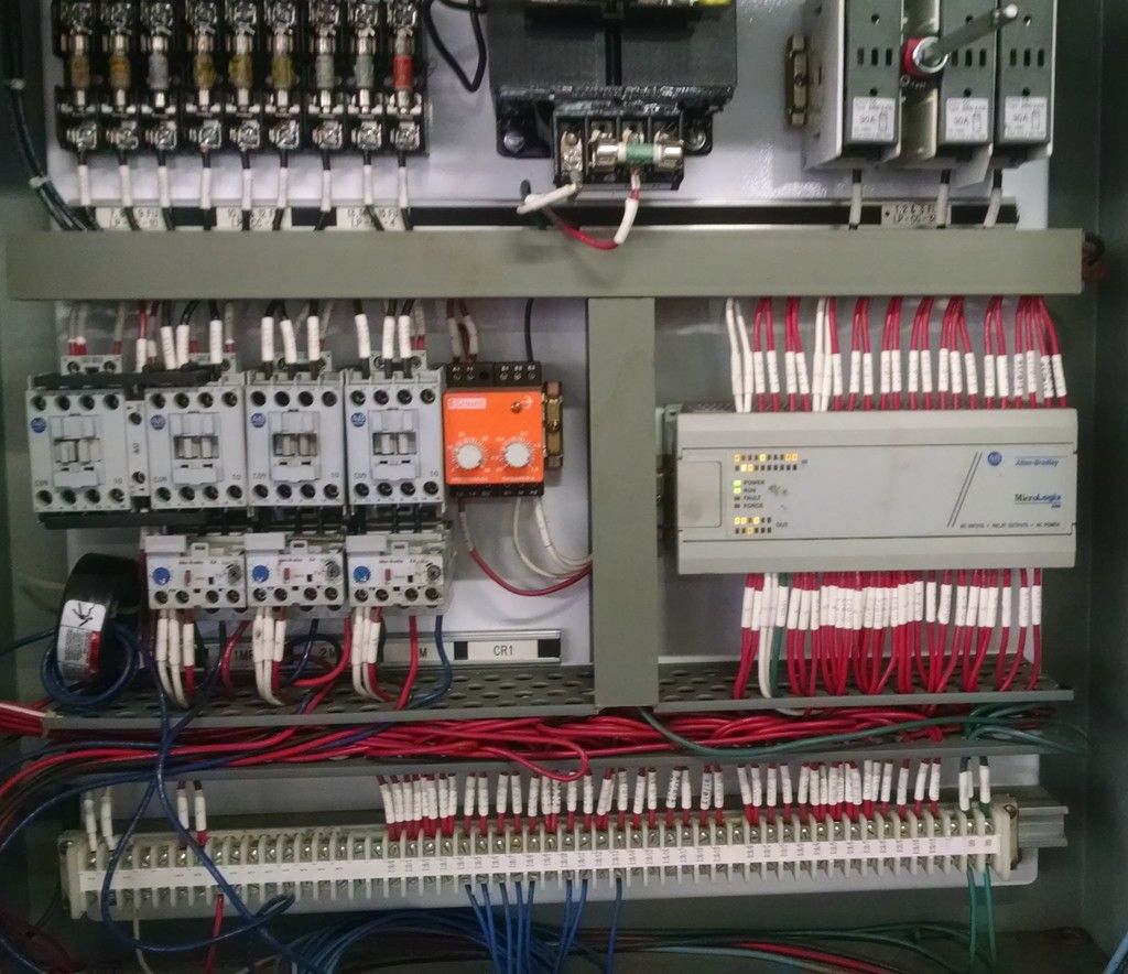
A total of three motors, and about 8 switches other than the operator controls, some photo-switch some standard AB limit switches. Not a complicated machine in the least but the PLC makes it tough (for me anyway) to try to figure out the sequence of operation.

This may be the company that made it http://www.z-loda.com/preEngineeredSystems.asp but that is my guessing by Google searching images of vertical conveyors. I did try calling them once already but no one answered. If so it would be the 300 model. Small bins, pretty fast speed.

I sincerely appreciate the response.
 
Is there any info on the conveyor itself?
mfg
installer
service company
???

the conveyor mechanicals and control panel were most likely a package
 
Is there any info on the conveyor itself?
mfg
installer
service company
???


Other than individual components I can find no markings at all.

There is a phone number written in sharpie on it that I am told is the service guy. Been the same guy for '15 years' but that is part of the problem, it has not been well maintained at all.

There is one limit switch still connected to the PLC but removed from its mount and sitting on the floor. I have little faith in this persons commitment to keeping the machinery safe.

Thanks for commenting.
 
Did it work before you replaced the photo-switch?

Well that is a good question.

It got the job done but I believe without a safety system in place for the unloading.

It seems if they do not keep up with the bins the vertical conveyor will keep trying to send more.


Here is an example of how well maintained it is.

I found this while following wiring.

IMG_20161219_120550921_zpsysoaixxl.jpg
 
161222-1018 EST

iwire:

--- The customer noticed that the LED indicators on one of the photo switches where out. They requested we replace it, we got the same model and it was a plug in replacement, I put in place, got the aim right and it seemed to work ----
You have now indicated that it has a separate power source, and a pot is used to set a threshold point. I have to assume that means this is a simple on-off switch with no other included function. You can also see the PLC input light change state in accordance with operation of the photo-detector.

--- we got the same model and it was a plug in replacement, I put in place, got the aim right and it seemed to work until the first bin went by a photo-switch beyond the one I changed.
"it seemed to work" what seemed to work? Did the replaced photo-detector still work after the bin went by the next photo-detector (meaning did the PLC input for the replaced photo-detector still respond correctly after the next photo-detector was transitioned)?

My guess is that each photo-detector is connected to only a single PLC input. If so, then you should be able to test each detector with its PLC indicator LED. If all of this is OK meaning that there is no intermittent connection between detectors and the PLC, then it would seem that we may have a PLC problem.

I had a problem at GM once where one of our machines would intermittently stop in mid cycle. The plant electricians had tried to spot the problem for over a month, then they called me. This was not the kind of problem where they could have had a person constantly watch the machine and ever find the problem. I could not have either. We had some idea of the logic area where the problem could originate. This was a PLC controlled machine, Modicon. I brought in my time logging equipment that can simultaneously monitor 8 binary inputs with 20 millisecond response time for as long a time as is reasonable. At least a day at a time. After a day of recording I was able to find that one PLC output was intermittent in its operation. A bad AC output module.

.
 
"it seemed to work" what seemed to work? Did the replaced photo-detector still work after the bin went by the next photo-detector (meaning did the PLC input for the replaced photo-detector still respond correctly after the next photo-detector was transitioned)?

I mean that the switch changes state when a bin passes it.

I went looking and here is a pdf about the switch, it is apparently more complicated than I thought. I was not provided any instruction with it, just the switch.

http://literature.rockwellautomation.com/idc/groups/literature/documents/in/9000-in002_-en-p.pdf

The model is Allen-Bradley 42GRU-9002-QD
 
That looks like a panel built in house. I have helped build several. Whoever did it did a nice job.

The problem with home brew panels is usually lack of documentation.

Bob, unless you are prepared to reverse engineer the control panel, you may be in for a rough time.

Why don't you have access to the PLC? Do you mean you don't have the connector or software, or is the connector somehow not accessible?
 
That looks like a panel built in house. I have helped build several. Whoever did it did a nice job.

No chance of that, this is a supermarket I really don't think the employees wired it.


Bob, unless you are prepared to reverse engineer the control panel, you may be in for a rough time.

Yes and I have tried to get out of it but I am the guy. :weeping:

Why don't you have access to the PLC? Do you mean you don't have the connector or software,

I would need Allen Bradley software and some clue how to use it. I doubt it is available for free download either.

The PLCs I usually work with have touch screens that allow access to programing, not so with this.
 
I would need Allen Bradley software and some clue how to use it. I doubt it is available for free download either.

The PLCs I usually work with have touch screens that allow access to programing, not so with this.

I found this that might help you:

http://literature.rockwellautomation.com/idc/groups/literature/documents/um/1761-um003_-en-p.pdf

You will also need a cable, and a program like RS Logix. I am familiar with them, but haven't touched an AB PLC since the SLC 5 days.
 
Thanks, almost 500 pages ...... yikes

Too bad there isn't any Cliff notes.

I scanned through it and it looks like there is some pretty straightforward info about connecting a computer to the Logix module and seeing the program on the screen.

I don't think you need a re-program. I think you need to be able to see what the Logix controller is telling the modules to do. You can't trust the lights on the modules 100%. Also, I have seen relays in some output modules fail, and that gets tricky.

Call around, you might be able to find someone that has a cable and a program already on a computer that can at least do a quick monitor of the ladder logic.
 
Status
Not open for further replies.
Top