How do I fix this?

Status
Not open for further replies.
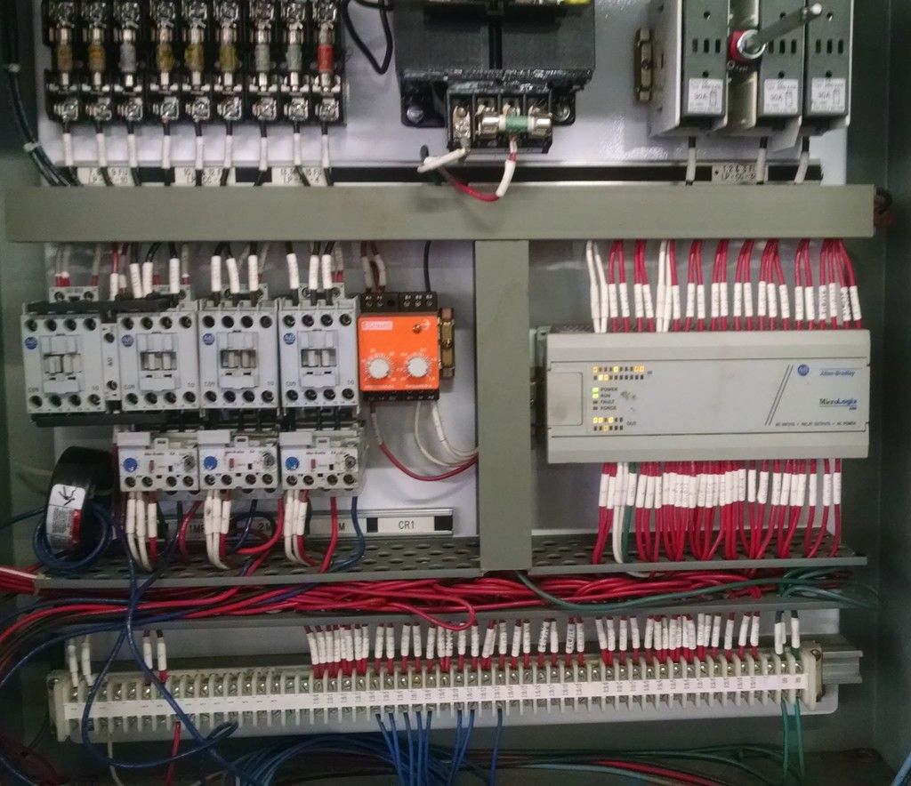
I don't think you need a re-program. I think you need to be able to see what the Logix controller is telling the modules to do.


I agree, I am not looking to change anything but I want to see how it is set up.

Call around, you might be able to find someone that has a cable and a program already on a computer that can at least do a quick monitor of the ladder logic.

That will be up to the boss.

Thanks for the help though. :)
 
I agree, I am not looking to change anything but I want to see how it is set up.


That will be up to the boss.

Thanks for the help though. :)

You are welcome.

I wish I was closer, I would come and take a look at it. It may not have been built by the employees of the supermarket, but it sure looks like a 'one off' to me. I helped build one for Bristol-Meyers, but I didn't work for them. It was to control a conveyor belt for a machine that put lids on cans.

Prior to that, I worked on AB PLCs and at first had only the lights to go by. I did that for a few months before I got sent to school and actually had a computer to work on the PLC machines with. That's why my caution not to trust the lights. The light may still give good info though.

Do you know which inputs the switches go to? If so, you can at least see if the switch is making it's assigned light(s) toggle. That's the cave man way, but it may be the only way. Been there, done that, glad I was getting paid by the hour kind of thing.
 
Do you know which inputs the switches go to? If so, you can at least see if the switch is making it's assigned light(s) toggle. That's the cave man way, but it may be the only way. Been there, done that, glad I was getting paid by the hour kind of thing.

I only verified that the switch I was changed was showing up at the input LED on the PLC. I have not done that with the rest..


By the hour for me as well, but I really feel strongly about fixing it right due to the untrained folks working around it.
 
Other than individual components I can find no markings at all.

This is partly why the NEC now requires nameplates on 'control panels'.

I would check with a local AB automation distributor. They probably have a customer list that includes a 'system integrator' that could download and print the program for you. Heck, they might even have an in house tech support person. I used to provide this type of support for a distributor, I got a lot of my work through contractors.
 
I just worked on a AB photo eye last week. Ive read that manual you posted and the only part I found useful was this section:

Sensor AlignmentThe red LED indicator is an alignment aid which indicates that a margin of 2.5X has been reached.This means that the sensor is receiving at least 2.5 times the signal strength back from the targetneeded to trigger an output signal. In general, it is desirable to have a higher margin to helpovercome any deteriorating environmental conditions, i.e. dust buildup on the sensor's lens. Whenaligning the sensor, the best performance can be obtained if this margin indicator is illuminatedwith the target in place. It is recommended to leave the sensitivity at its default maximum settingand change it only when necessary.Transmitted Beam Versions

1. Visually align the emitter and receiver units (emitter and receiver fibers) until the green output LEDturns ON (with light‐operate mode) or turns OFF (with dark‐operate mode).

2. To be certain that the beam is centered, it is required to sweep the emitter or receiver in the horizontaland vertical plane and determine at what position the output indicator goes ON and then goes OFF.Set the sensor (or fiber optics) midway between both positions. The red margin LED should also be ONwhen the beam is unbroken.


999 time out of 1000 if the PLC is up and running for years and years you can fix the problem without going online with the processor. Its some physical I/O that has gone bad. Of course it makes it much easier to trouble shoot if you can see the logic.


I've seen programmers do tricky stuff with reset buttons also. Sometimes you have to hold down the reset button for 30 seconds before a fault will clear.

I would check all the fuses (Im sure you started there), tighten all wire terminations, and I'd also double check that E-Stop.

Things are a lot easier if there are wiring diagrams. Its probably something simple like a stuck limit switch.


Good luck!
 
161222-1234 EST

iwire:

Call the photo-detector location where the original detector failed Photo-1, and the next location after it Photo-2.

After the new photo-detector was installed at Photo-1 it worked. I assume this means that the input LED at the PLC for this detector also worked as expected in a direct on-off respect, and with no time delays.

Then a bin was moved on the conveyor and when it reached Photo-2 position something did not work. What did not work? At this time does changing the state of Photo-1 detector produce a corresponding expected change in the Photo-1 input at the PLC?

Also at this time and before did the LED at the PLC for Photo-2 work as expected?

.
 
Got a make and model on the photo eye? Not sure why it might matter, but you never know.

One possible thing to look for is that sometimes in systems like this; a photo eye not working gets the entire sequencing out of whack and it can't recover on it's own. SMART programmers will put in a "Reset" or "Homing" function, often initiated by a simple switch and in many cases, that switch is NOT on the door to avoid having operators use it incorrectly. It may be a switch or button INSIDE of the panel.
 
Last edited:
161222-1357 EST

iwire:

Jaref has brought up a good point. If this is an AB PLC then it may have the posibility of operating in what is called a "sequencer mode" as contrasted with what I would call a "combinatorial logic mode". I don't believe Modicon ever had a sequencer mode. For any machine I ever worked with, a sequencer would be or was a disastor. A sequencer might be useful on a conveyor, I don't know. A sequencer may require some sort of reset to get things back in sequence.

Although many machines might appear to operate on a specific sequence, there are times when one does not need or want to be tied to a specific sequence. A machine jams, I want to get home by some path, but don't want to or can't follow the the normal sequential path.

.
 
I agree, I am not looking to change anything but I want to see how it is set up.


That will be up to the boss.

Thanks for the help though. :)

Call your local Allen-Bradley distributor. They will usually have an A-B teck-rep on staff. Ours is very helpful. I don't recall seeing which A-B PLC is involved. Is it a PLC5, SLC500 or micro-logix, Control logix or what? A-B (Rockwell Automation) software licensing IS pricy, but if it's a PLC5, you can usually find a software download for RSLogix5 that gives a 7 day activation. The software download is free, it's the license thats expensive!
 
161222-1234 EST

iwire:

Call the photo-detector location where the original detector failed Photo-1, and the next location after it Photo-2.

After the new photo-detector was installed at Photo-1 it worked. I assume this means that the input LED at the PLC for this detector also worked as expected in a direct on-off respect, and with no time delays.

Then a bin was moved on the conveyor and when it reached Photo-2 position something did not work. What did not work? At this time does changing the state of Photo-1 detector produce a corresponding expected change in the Photo-1 input at the PLC?

Also at this time and before did the LED at the PLC for Photo-2 work as expected?

.

Another question I might ask is about said abandoned limit switch. Was that removed to make the machine functional after the PE failed? With the PE replaced, is it possibly waiting for something to "make" that limit switch?
 
Call your local Allen-Bradley distributor. They will usually have an A-B teck-rep on staff. Ours is very helpful. I don't recall seeing which A-B PLC is involved. Is it a PLC5, SLC500 or micro-logix, Control logix or what? A-B (Rockwell Automation) software licensing IS pricy, but if it's a PLC5, you can usually find a software download for RSLogix5 that gives a 7 day activation. The software download is free, it's the license thats expensive!

The pic looks like a Micro Logix 1000. That's what I gave him a pdf for, anyway.

I am sure it's not a PLC5 or a slick500.
 
Another question I might ask is about said abandoned limit switch. Was that removed to make the machine functional after the PE failed? With the PE replaced, is it possibly waiting for something to "make" that limit switch?

The limit switch sitting on the floor seems to have been like that for a very long time. If I operate it everything stops and I have to hit a reset button.

I will get back to everyone's responses after some sleep*, I do appreciate them all.

Just really overtired right now and a little fuzzy, I want to be on my game when talking to all of you about it.

(*I work very odd hours, days, nights, both :roll: )
 
I only verified that the switch I was changed was showing up at the input LED on the PLC. I have not done that with the rest..


By the hour for me as well, but I really feel strongly about fixing it right due to the untrained folks working around it.

I have no reason to think that you wouldn't feel the same even if there were no untrained personnel working around the conveyor. By 'cave man' I meant not having a computer, I didn't mean making stone age repairs. Which I don't. Never have. Never will.

OK, so your switch lights up the LED. What you don't know is if the input is being seen by the PLC.

Is the LED in an outboard (expansion module) device, or is it one of the inputs on the main unit? If it's external, there is an easy place to do a part swap.
 
The pic looks like a Micro Logix 1000. That's what I gave him a pdf for, anyway.

I am sure it's not a PLC5 or a slick500.

The pics didn't show up on my laptop, and they don't alot of times for this forum, so just guessing. The software wouldn't be much help anyway, since the PLC5 and SLC500 don't store the documentation in the processor. You have to have the original program on the pc you're using to access it. Micro-logix and Control-logics, on the other hand, use controller tags instead of octal or decimal numeric addressing.
 
It is a ML1000. I have several used ones on the shelf.
Software does you no good if they protected it. I've never worried about doing that but some do.

I could send you an old laptop with software and cable if you're hurting, but the suggestion about the local AB distributor is a good one. They will know who.


(Just don't let AB know I offered.)
 
I mean that the switch changes state when a bin passes it.

I went looking and here is a pdf about the switch, it is apparently more complicated than I thought. I was not provided any instruction with it, just the switch.

http://literature.rockwellautomation.com/idc/groups/literature/documents/in/9000-in002_-en-p.pdf

The model is Allen-Bradley 42GRU-9002-QD

I work in a paper mill and we use these same sensors for sheet detection. If they both seem to work correctly, which it sounds like they do, verify the "light/dark" setting. Or simply change it from one to the other and see if it fixes it. The Photo eye will still function correctly even if it is on the wrong setting but the PLC won't recognize it. I agree with others that unless the PLC logic has been flawed from the start, it is extremely unlikely your problem.
 
I have been tasked with fixing a vertical conveyor system. The customer noticed that the LED indicators on one of the photo switches where out. They requested we replace it, we got the same model and it was a plug in replacement, I put in place, got the aim right and it seemed to work until the first bin went by a photo-switch beyond the one I changed.

Heres the thing though, I can't find any documentation or manufacturers name on the control panel. Further more it is controlled by a PLC without any means of accessing it.

What would you guys do?

Here is the inside

IMG_20161219_111120577_zpsereflh8f.jpg


And the cover

IMG_20161219_111153963_zpsiyihstyt.jpg


From left to right

Stop, Cycle start, waiting to unload, jog forward, jog reverse, fault reset, load fault, unload fault, over torque.

The photo-switch I am working with seems to be part of the unload fault programing.

Where would you start?
A couple of other thoughts to add to the excellent advice you've been given.
At a guess, I'm inclined to think it isn't a PLC problem. They can and do fail of course. But it would usually affect more than a sensor.

I assume you've checked the tightness of all the connections and terminals.
Are the photocell lenses clean?
Are the photoswitches expensive? If not, you might consider replacing them all.
 
Go buy a cheap laptop at WalMart. Spend whatever money you need to. Do the job and leave the laptop with the manager at the store. He will now have what is necessary to maintain his equipment. Do it all at his expense.
 
There are a 'boat load' of wires between the PLC and the field terminal strip, however it looks like there are only a handfull of field devices.

My guess is that the PLC is 'out of sequence' with the real world. For some reason, these are often hard to re-establish if you do not know the secret handshake.
Heaven forbid, if the original program designer expected this to be job security where they had to be called in for servicing. Proprietary systems are definitely a bad idea when the 'proprietor' is no longer in business.
Any PLC ladder diagram is better than nothing.
 
Status
Not open for further replies.
Top