Just a thought........What exactly is your 'K' value (I've seen at as 'A' elsewhere, referred to as a constant). If this is NOT a cmil value, then what is it exactly, and how is it derived?
Can you try it in SI units? It is simpler than Imperial.
Just a thought........What exactly is your 'K' value (I've seen at as 'A' elsewhere, referred to as a constant). If this is NOT a cmil value, then what is it exactly, and how is it derived?
@K8MHZ No, no... not trying to come up with a fuse. What I'm wanting is to determine a value for any size AWG conductor for any material, that ballparks the highest current it can withstand before it fails. I'm trying to determine my ideal 'outside' value for such. So that in other calculations I'm doing for a larger project, I know if I've got a flyer, or if my equations are generating reasonable results that I can then go test and/or work backwards from in terms of derating etc.In essence, are you trying to design a fuse?
It's been my experience that the results from a 10 minute test will trump the results from 3+ hours of math, every time.
I don't think it's possible to come up with a simplistic answer like such and such a metal of a certain diameter will melt at exactly a calculated current. There are other factors do be concerned with. What if you somehow come up with a value for a certain diameter, how will that transfer to a different shape?
I spent a couple years in R&D as a metallurgical technician. One of the projects designing superalloys for jet engines. EVERYTHING was tested. The math just got us in the ballpark. You will need to do a gradient test and identify the incipient melt point to come up with an exact phase change temp and that will only work for that specific shape / size, etc.
Also, your tests must be repeatable. Once you are comfortable with the results, then do the math. That is now that you have the answer, create the math that explains it. That will get you closer for the next test. Sorry, but that is just how it works. Math alone won't do it.
I've tried both and neither comes up with the 10,224 value for K used by @gar, I believe.Just a thought........
Can you try it in SI units? It is simpler than Imperial.
@winnie I just saw this- let me digest this... _thanks!_My apologies for not being clear. The above is not a temperature equation, it is simply Ohm's law re-written for power dissipation:
E = I*R (Voltage = current times resistance)
P = E * I (power = current * voltage)
P = I^2 * R (power = I square R)
R = (specific resistivity) * (length) / (cross section) ( resistance is proportional to length and inversely proportional to cross section)
The SI unit for specific resistivity is the ohm meter. At 20C copper has a specific resistivity of 1.68*10^-8 ohm meter
(also 2.043*10^-8 ohm meter at 75C)
Consider a wire 1 foot long with a cross section of 1 circular mil
R = 2.043*10^-8 (ohm*meter) * 1 foot * 0.3048 (meter / foot) / ( 1 cmil * 5.06707*10^-10 (m^2/cmil)) = 12.3 ohm
This is where the 'K' factor of 12.3 comes from in many voltage drop equations. It is simply the resistivity of copper expressed in ohm cmil per foot
In my equation above if you have 30A of current flowing in a wire 1 meter long with a cross section of 6 mm^2:
30A^2 * 2.043*10^-8 (ohm meter) * 1 meter / ( 6*10^-6 meter^2) = 3.065 A^2 ohm = 3.065W
6mm^2 wire carrying 30A has to dissipate about 3 W / meter. Since resistance changes with temperature, the exact dissipation to carry this current will change with temperature.
A bit of confusion above: The 'K' that I was talking about is the electrical resistivity of the copper, not the thermal resistivity of the air. Since the general concept and the math is the same for both, and this discussion involves both, I should have more clearly distinguished the two. And to add even more confusion the unit for thermal conductivity is watts per meter per kelvin, or W/ m K...so that letter K shows up in three different usages (electrical resisitivity constant, thermal conductivity constant, and degrees Kelvin)
When current flows through an electrical conductor, there is some resistance and overcoming that resistance requires voltage. Voltage * current = power, and the resulting thermal power needs to be dissipated or the conductor will heat up. Electrical resistance determines the amount of voltage and thus the power dissipated to permit a given current to flow.
When heat flows through a thermal conductor, there is some thermal resistance and overcoming that resistance requires a temperature difference. Thermal resistance determines the temperature difference needed to permit a given amount of heat to flow.
The thermal conductivity of air is 0.024 W / m K (note: this is a conductivity, not a resistance, so watch out for the trap of confusing the two) This same value could be expressed as 41.7 "thermal ohm" meter where watts per kelvin show up in the same way that amps/volt show up for electrical conductivity
To figure this from basic equations requires solving Fourier's law of heat conduction, but for your purposes you are going to run into a significant complication: the thermal resistance of still air doesn't help you when the air can move, and because air is subject to convection from heat it will move. I can only point you in the direction of the issue, I don't know how to solve for heat conduction with moving air.
-Jon
Units of what? Where is/what is it referenced?I've tried both and neither comes up with the 10,224 value for K used by @gar, I believe.
@K8MHZ No, no... not trying to come up with a fuse. What I'm wanting is to determine a value for any size AWG conductor for any material, that ballparks the highest current it can withstand before it fails. I'm trying to determine my ideal 'outside' value for such. So that in other calculations I'm doing for a larger project, I know if I've got a flyer, or if my equations are generating reasonable results that I can then go test and/or work backwards from in terms of derating etc.
I'm looking for an ideal value because at a minimum it simplifies (or should simplify) initial calculations. If the max ideal amperage a 14AWG Copper wire can take is actually 166A, I want to know how that was calculated so I can repeat it. And I want to know how to do that with other metals.
As an example- what is max the current a 42AWG 1-foot long piece of Nichrome60 wire can handle? Nobody knows. is it 10mA? 500mA? Millions of feet of this wire are made every year... and nobody can tell me how much current it can handle before it fries ideally or with everything else calculated in.
I'm not really concerned larger conductors. It's the small ones, beyond 40AWG that are giving me the biggest problem because there is very little information in any table for wiring of this size.
-C
I'll say continuous on duration- either it will handle it or it will melt. If it's at the melt temp, then I know to stay below that. Open air. Solid core. DC only. This is purely about direct maximum energy the conductor can handle in open air to be at the fry point, so I know to stay below it by a good margin. Right now the ONLY definitive thing I have is the melt-point of copper (or any other metal/alloy I look at).Understood.
One thing I noticed is no attention paid to the duration of the current. Are you just assuming it to be the NEC definition of 'constant'? Which would be in line with an 'outside' value.
Some other variables to be considered....solid vs. stranded. AC vs. DC. 120hz vs. other frequencies. 12 volt vs. higher.....free air or enclosed?
Repeating the experiment to run 166 amps through a 14AWG copper wire for 3+ hours would be fun. Then you would have to do 167 amps to make sure the 166 was accurate.
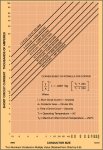
@winnie I beg your pardon- I've seen this as a foot not in several AWG tables (like this) regarding power transmission as opposed to chassis value for ampacity:
What exactly is your 'K' value (I've seen at as 'A' elsewhere, referred to as a constant). If this is NOT a cmil value, then what is it exactly, and how is it derived?
I've tried both and neither comes up with the 10,224 value for K used by @gar, I believe.
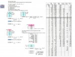
Okay, let me play with that and see what I can come up withI believe I can tell you where that number comes from.
My guess is that it is ohms cmil / kilofoot at 20C.
R = 1.68*10^-8 (ohm meter) * 1000 feet * (0.3048 meter/foot) / ( 1 cmil * 5.06707*10^-10 (m^2/cmil)) = 10106.
Okay, I missed by a percent, but you get the idea.
-Jon
@winnie My problem with NEC 310.16 (and much of NEC's other documentation on the matter) is that is not inclusive. It covers a few AWG sizes, none that I'm really interested in, and for others they pick arbitrary values based on fuzzy logic only they know of- not published formulas. My frustration stems from the fact that once people start using tables, the original knowledge, logic, and JUSTIFICATION for the values in the tables is lost- which should *NEVER* happen from an engineering standpoint. Tables are meaningless without published, reviewable, equational and empirical data and reasoning to back the table values up.I see that 700 circular mil per amp, but the only place where I've seen something similar is for designing windings in electric motors, where you have lots of wire packed together and so the surface area of an individual wire is quite meaningless.
The above table simply does not match the electric code table, do a search for NEC 310.16 and you will see what I mean.
I was using the K factor for the electricial resistivity of copper, expressed in ohms for 1 foot length and 1 circular mil cross section. I derived it from the specific resistivity of copper given in ohm meters. That value can be calculated using quantum mechanics, but I don't understand that aspect well enough to explain it.
I also used K to mean degrees kelvin, and tried to make it clear the difference.
-Jon
@winnie My problem with NEC 310.16 (and much of NEC's other documentation on the matter) is that is not inclusive. It covers a few AWG sizes, none that I'm really interested in, and for others they pick arbitrary values based on fuzzy logic only they know of- not published formulas. My frustration stems from the fact that once people start using tables, the original knowledge, logic, and JUSTIFICATION for the values in the tables is lost- which should *NEVER* happen from an engineering standpoint. Tables are meaningless without published, reviewable, equational and empirical data and reasoning to back the table values up.
I'm still sort of where I started at. The only actual way, based on pure physics, to find maximum amperage a bare conductor of any material of a given AWG size can handle before it melts is to determine maximum free electrons in 1cmil of conductor and do a coulomb to amp conversion and scale it. Derating is irrelevant. Dissipation is irrelevant. All that is tertiary to simple physics. This will provide the absolute maximum amperage value that is possible in an ideal condition for 1 second or more through a conductor. I can derate from there.
I want to thank all you really cool guys for helping this little geeky girl out.
xoxoxo -C
")