Thank you for all the input. To answer a few of the questions...
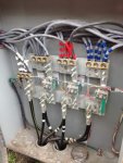
- The load side terminals are rated for two conductors.
- There are two sets of service entrance conductors, and the utility is actually adding a third to compensate for the potential backfeed. That is how I got the picture when they opened to see how much work they were getting into.
- I have asked and gotten approval from the utility to land in the CT cabinet. I am just not sure how to accomplish that at this point.
I need to offset the meter so tapping the service conductors will do me no good. I thought of possibly bolting on one of those stacked terminal lugs if it will stick out far enough, but then I am afraid of blocking the set screw for the existing lugs. Were you thinking I could use a Polaris connector to combine some of the existing wires and free up space?