Ignition System Circuit Interpretation

Status
Not open for further replies.

GaryDG

Member
Location
Oregon
I have attached a ignition circuit diagram for an ATV and wish to confirm the meaning of the diagram and the testing method.

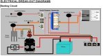
The ignition switch has 6 connectors marked A,B,C,D,E,F. See attachment,right hand side.

I don't think I am interpreting the circuit correctly.

Key in "off" position there is continuity between E&F, and no continuity elsewhere

Key in "on" position there is continuity between C&D, and no continuity elsewhere

Key in "start" position there is continuity between A&B, and no continuity elsewhere, including C&D

I am not certain what that small two-sided arrow nor the red line between D&E signifies, can you clarify?

Thanks!
 

Attachments

  • 2016-05-11_11-09-16.jpg
    2016-05-11_11-09-16.jpg
    49.6 KB · Views: 0
I read that as indicating that the entire horizontal bar moves between the Off and On positions, shorting C to D in one position and shorting E to F in the other.
The A to B connection is shown as a push button or momentary contact.
The diagram is not explicit in showing that Off and On are maintained position and Start is a spring loaded motion from On, nor does it convey by itself that the C to D connection is opened when switching to Start. (With the Start Diode providing power to the ignition while C and D are open.)
 
I am so glad I am out of that business. Having to work with those diagrams sucks.

Are you having a 'no start' problem?

How many wires are there going to the start switch? Does the diagram wiring scheme match the actual wiring on the vehicle?

I did vehicle systems repairs for about 20 years and the diagrams are terrible. They make up their own symbols and there is no industry standard. I had to do tons of reverse engineering.
 
I read that as indicating that the entire horizontal bar moves between the Off and On positions, shorting C to D in one position and shorting E to F in the other.
The A to B connection is shown as a push button or momentary contact.
The diagram is not explicit in showing that Off and On are maintained position and Start is a spring loaded motion from On, nor does it convey by itself that the C to D connection is opened when switching to Start. (With the Start Diode providing power to the ignition while C and D are open.)

That's how I see it, too. The diagram shows E and F not being used. I wonder if that's true on the ATV.
 
Thank you!
That interpretation is consistent with what I thought about continuity.

You comment "The diagram is not explicit in showing that Off and On are maintained position and Start is a spring loaded motion from On" thanks for that too, the switch, physically, is maintained in Off and On but spring loaded in Start, that is .

So the question is if C&D are closed in Start. I guess I could test with a known good switch.

Thanks again!
 
Solution

Solution

Thanks again to everyone that responded!

Yes, I had a crank no start issue with my Polaris. Fortunately while testing that ignition switch I found a loose connection of three wires at a post under the hood. I had checked for loose connections but somehow missed that one. I connected and reinstalled the switch and it now works!
 
... Key in "start" position there is continuity between A&B, and no continuity elsewhere, including C&D ...
That's the problem: it's turning the ignition off while the starter motor turns.

...I am not certain what that small two-sided arrow nor the red line between D&E signifies, can you clarify? ...
It indicates a double-make, double-break, double-throw switch.

The C-D contacts are used with an ignition system that relies on battery voltage.
The E-F contacts would be used with a magneto ignition, which needs to be shorted to ground to turn it off.
 
That's the problem: it's turning the ignition off while the starter motor turns.

If you look at the rest of the circuit, I think that you will find that the "Start Diode" supplies the ignition while cranking, getting power from the A-B connection. That is the start position powers starter motor and ignition while the On position powers the ignition only.
The diode is doing the job that a different contact configuration within the switch would otherwise do. In some cases (not this one apparently) the Start position also de-energizes some or all of the Accessory circuits to minimize battery drain while starting.
 
Thanks again to everyone that responded!

Yes, I had a crank no start issue with my Polaris. Fortunately while testing that ignition switch I found a loose connection of three wires at a post under the hood. I had checked for loose connections but somehow missed that one. I connected and reinstalled the switch and it now works!

Good job. I'm glad you found it without spending a bunch of time hunting it down.

Next time, instead of checking for continuity, use a test light and test for voltage. I have found that to be a faster method that results in fewer headaches.
 
That's the problem: it's turning the ignition off while the starter motor turns.


It indicates a double-make, double-break, double-throw switch.

The C-D contacts are used with an ignition system that relies on battery voltage.
The E-F contacts would be used with a magneto ignition, which needs to be shorted to ground to turn it off.
How old or was there ever an ATV with a magneto ignition system? I remember some three wheeled predecessors of today's ATV's from the 60's and 70's that likely did have magneto - but also did not have anything that was battery powered and a pull cord for starting.
 
Status
Not open for further replies.
Top