Induced voltage (I think)

Status
Not open for further replies.

Rick Christopherson

Senior Member
Then you should have absolutely no difficulty in providing supporting information for your opinion rather making it incumbent on me to search for it.
There are so many references that I am not going to pick one over the other so you can nitpick some other detail. The references are broad.

I have given you my technical reasons for suggesting that it might not be such a good idea.
I haven't said yours were wrong.
Yes. You have presented those ideas, and I have countered them. What you haven't done is found a way to dismiss my counter statements.

I am open to discuss the topic in a civil maner, but if you are at the point of doing nothing more than sniping, then I am done. If you can't argue the points on their merits, then there is no point in pretending that this is a discussion any more.

I will respond to valid argument points made, but this will be my last comment on sniping comments. Post something with content, or I will not respond.
 

mivey

Senior Member
Rick,

As you have noted, heat due to a reduced impedance is the biggest concern for using an AC solenoid with DC. The speed of the solenoid may also be an issue for some applications.
 

mivey

Senior Member
Then you should have absolutely no difficulty in providing supporting information for your opinion rather making it incumbent on me to search for it.
I have given you my technical reasons for suggesting that it might not be such a good idea.
I haven't said yours were wrong.

Its a maybe thing, but Rick's statement was not completely correct. See page 7 here where you can use an AC solenoid with DC:

http://www.detroitcoil.com/PAGES/appdata.pdf

Therefore the question of whether or not a given AC unit performs satisfactorily on DC power depends upon how pull-in force and overheating can be balanced.

Some applications may not require that the solenoid be HELD energized. In this case, an AC design unit might be operated on either AC or DC power.
...
In many cases, AC solenoids can be operated on DC power with the addition of a switch and resistor.

However, the DC solenoid can be used with AC:

Within limits, DC solenoids can be operated on AC.
...
Therefore, the use of AC power on DC solenoids should be limited to applications where a low current is adequate, to prevent overheating. AC power is also practical where the solenoid is on and off in so short a time that the eddy current losses cannot generate excessive heat.
 

Besoeker

Senior Member
Location
UK
There are so many references that I am not going to pick one over the other so you can nitpick some other detail. The references are broad.
If you won't provide one, that's fine. If your basis for not doing so, and it appears to be, is that it might not support your position, that's fine too. Just maybe interesting.

Yes. You have presented those ideas, and I have countered them.
You have stated your opinion without any giving any technical basis for it.

What you haven't done is found a way to dismiss my counter statements.
What you haven't done is to provide a jot of support for your opinion.

I am open to discuss the topic in a civil maner, but if you are at the point of doing nothing more than sniping, then I am done. If you can't argue the points on their merits, then there is no point in pretending that this is a discussion any more.
I will respond to valid argument points made, but this will be my last comment on sniping comments. Post something with content, or I will not respond.
I'm also open to discuss it in a civil manner.
I've given reasons why I think the inclusion of a series diode would be a bad idea. Normally I would support my points with actual experience but I have had not a lot to do with solenoids - not that I have seen any reference other than your own that the coil in the opening post is actually a solenoid. What I can tell you is that if you try to switch a relay coil (or any other coil for that matter*) in a DC circuit without come quenching device across it like a flywheel diode there is a distinct probability that you will damage the switching element. You will no doubt be aware that IGBTs in variable frequency inverters have inverse parallel diodes. You can't just switch off the current in a coil.

Here's an actual circuit of ours to illustrate what I mean:

Triggercircuit.jpg


So, let's assume that we go with your idea of puting a series diode in the circuit and take the precautionary measure of fitting a flywheel diode across the coil. What will happen?
In the first half cycle the current will be at a certain value >0A. This current will then flow for a while in the flywheel diode and, given the relatively low forward drop on the diode, may still be flowing at the start of the next positive half cycle. So more current is established.....etc.

Without the flywheel diode, the current in the first positive half cycle will continue, as it must, into the negative half so the coil will see part of the negative voltage as well. How much will depend on the coil characteristics.

Mivey kindly provided a link to an article on solenoid operation and directed attention to operation of an AC solenoid on DC. On AC there is an initial inrush that gives pulling power while the closed holding current is much lower. This can be emulated on DC by having a series resistor switched in after closing.

From page 7 where Mivey directed us:

In many cases, AC solenoids can be operated on DC power with the addition of a switch and resistor. The switch is arranged to be opened when the solenoid closes. When the switch opens the resistor is in series with the solenoid coil. The addition of this resistance reduces the coil current so the solenoid can be held energized without burning out. A high current which will produce a high pull-in force is then possible.

This exactly the circuit that was commonly used on old DC switchgear where contactor coils were DC. The series resistor was called an economy resistor. And just a tad more sophisticated than a series diode.

*Other coils and DC.
A few years ago, well, actually several decades ago, we'd made some upgrades to a DC drive system that first saw the light of day in 1935 or thereabouts. The speed reference was a frequency from a master alternator driven by the DC master motor. It wasn't very big, maybe about 5kW and 310Vdc. This DC motor was started by shorting out a series of resistors in sequence with a final contactor shorting out the lot. Thus the intermediate contactors had only to make current, not break it and, as was the practice, were not DC rated. One not so fine day, the electrician working with me made some modifications but didn't explain them very well - this was in the far east so there were some language constraints. The long and the short is that one of the intermediate contactors tried to break the DC. It did so - eventually. When the molten contact material dripped out the bottom.
 

jumper

Senior Member
I have not figured out if the OP had a solenoid valve or not.

OP said this:

The coil between c and d is a 120 VAC operated contact in a valve positioner control cabinet. Anything greater than 22 VAC is sufficient to energize it, thereby opening the corresponding valve. Anything less than 8 VAC is de-energized which closes the valve. The area between 8 and 22 VAC is designated 'undefined' by the instruction manual, which I'm guessing means it could go either way.

The a side of the 120 VAC is the line and the b side is the neutral.

Now, when the contact is closed I have 120 VAC on the coil and the valve opens. No problem. However, when the contact is open I have 50 VAC on the coil which keeps the valve open. This 50 VAC manifests itself on the d side of the coil (referenced to ground). The voltage on the other side of the coil, using the same reference, is less than 1 VAC. We checked the contact and it is working. This voltage 'appears' on the conductor between e and d.

and this:

Yes, it is rated for 120 VAC. The valve positioner control enclosure, which is where my problem is, simply takes this 120 VAC as a logical '1' and sends a different signal to open the valve. This 120 VAC is not opening the valve, it is simply generating the command to open the valve. The 50 VAC mystery voltage is also being interpreted as a logical '1' though.

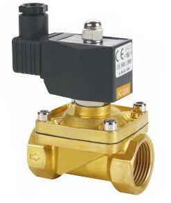
This does not seem to describe a typical solenoid valve to me. I am not seeing this:

solenoid_valve_1.jpg


from the OP's description. :?
 

Besoeker

Senior Member
Location
UK
Hmmm? We're discussing solenoids but I don't see a single solenoid in your example circuit. :slaphead:
I don't recall that the OP mentioned a solenoid. Just a coil.
The circuit I presented has a coil as does a solenoid. It has a semiconductor device that passes current in one direction just like your diode.
So it is entirely pertinent to your circuit suggestion.

You stated that you were open to discussing the topic in a civil manner. Accordingly, I made the points in a civil manner and provided real life information.
If you are now no longer open to discussing the matter in a civil manner (or otherwise if you see fit) that's fine.
 

gar

Senior Member
Location
Ann Arbor, Michigan
Occupation
EE
121216-0900 EST

jumper:

drbond24 gave a generic (colloquial) description of the circuit in his first post. The load was called a "coil". And by use of the words "operated contact" in that first sentence you were probably led to assume an electromechanical relay.

Both from the nature of the problem (my assumption of a capacitive coupling problem, likely cable lengths, and later as possible leakage in the "contact between e and f is a control system relay output" (possibly a solid-state contact with a snubber) ), and the operating power levels at pull-in and drop-out (1.8 mA or thereabouts at 8 or 22 V, don't know which) ---- implies that the item called a "coil" is a solid-state device.

This is further implied by the impedance of the "coil" being stated as 12,000 ohms. Essentially all resistance. Only divulged late in the posts. Once the 12,000 ohms was specified, then it became clear that 1.8 mA is at 22 V. This is a power level of 40 mW. It takes an extremely sensitive electromechanical relay to pull-in at this power level. A quick check indicates that 24 V DC reed relays are in the range of 3000 ohms. Thus, almost certainly the "coil" thing is not an electromechanical relay, but is a solid-state interface.

.
 

kwired

Electron manager
Location
NE Nebraska
I have not figured out if the OP had a solenoid valve or not.

OP said this:


and this:


This does not seem to describe a typical solenoid valve to me. I am not seeing this:

solenoid_valve_1.jpg


from the OP's description. :?
Trust me, I am just as lost as you. I think the OP had some solid state devices somewhere in his circuit and not (both) true dry contact and true coil in his circuit. He was experiencing some kind of "bleed thru" current as a result that was enough to allow undesired operation. Simple "bleed resistor" installed in the right place was likely the solution. I think somewhere in there OP did solve his problem, but it kind of got overlooked in the rest of the conversation.

These guys have more less hijacked the thread with speculation and have gone off in another direction with things that may not even be there. But that never happens on this forum.;)
 

Open Neutral

Senior Member
Location
Inside the Beltway
Occupation
Engineer
I'm late to the party but..... I have used a form C contact in one case; i. e. not just opened the supply to the load but actually shorted the load out to insure it did not falsely actuate.
 
Status
Not open for further replies.
Top