How long has this transformer been in service? Is there any oil sample data? Has the oil been processed recently or since the problem was noted? Do you have an oil level indicator?
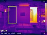
Oil could be sludging causing an obstruction at the bottom. An air pocket could be present in the top of the left radiator.
Do you have a digital camera image (photo)?
Sorry, a lot of questions.
Hi so unfortunately I don't have any recent oil sample data. :happysad: The latest was 2008 but it was ok then. The oil level was 25%, the temp was 50 deg C. I am awaiting to find out the health of the nitrogen blanket.... Will need to organize an oil sample