Installing surge protectors in an I.S circuit

Status
Not open for further replies.

KentAT

Senior Member
Location
Northeastern PA
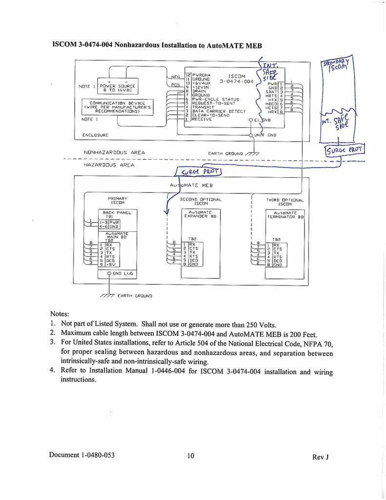
Is it permissible to add surge protectors to an intrinisically safe circuit without them appearing on the intrinsically safe device's approved control drawing?

More specifically, we have an intrinsically safe flow measurement system operating in a Class 1, Div 1 building (outside is Div 2). The customer who is receiving the natural gas from our pipeline (local gas company) will be adding a circuit to our system so they can also receive the identical measurement values. They are concerned about surge protection and want their circuit to be as follows:

PLC (uncl). > barrier (uncl) > surge prot (uncl, but rated Div 2) > field wiring underground > above ground JB w/ surge prot (Div 2) > into Div 1 > into intrinsically safe enclosure/system.

The seals, etc are not an issue as all will be done properly. I just never added or changed anything on an I.S. control drawing before.

The surge protector is an MTL Instruments model SD16, which MTL shows in their product brochure as being approved for such installation.

Kent
 

KentAT

Senior Member
Location
Northeastern PA
...missed the editing time limit - clarified the following sentences and added attachments . Kent

KentAT said:
...They are concerned about surge protection and want their intrinsically safe circuit to be as follows:

PLC (uncl). > barrier (uncl) > surge prot (uncl, but rated Div 2) > field wiring underground > above ground JB w/ surge prot (Div 2) > into Div 1 > into equipment enclosure.

The MTL model SD16 is specifically on pages 5 and 6 of the attached product brochure (don't know how to post over the allowed file size - sorry)

View attachment 1950

View attachment 1951

View attachment 1952

View attachment 1953


Kent
 

rbalex

Moderator
Staff member
Location
Mission Viejo, CA
Occupation
Professional Electrical Engineer
Associated Apparatus appearing (or at least referenced) on the Control Drawing is a fundamental requirement of Section 504.10 (A). It is certainly possible that the Control Drawing may in fact recognize adding surge protection. Without having the Control Drawing, it is impossible to say whether the MTL SD16 would be acceptable.

How would the circuits “…receive the identical measurement values…” without some form of interconnection between the circuits?
 
KentAT said:
...missed the editing time limit - clarified the following sentences and added attachments . Kent


The MTL model SD16 is specifically on pages 5 and 6 of the attached product brochure (don't know how to post over the allowed file size - sorry)

View attachment 1950

View attachment 1951

View attachment 1952

View attachment 1953


Kent

I think you can circumvent the whole issue by installing your barrier in the Div. 2 area, just before netering the Div. 1 area. PLC>SP>UG>SP>ISB>Device
 

rbalex

Moderator
Staff member
Location
Mission Viejo, CA
Occupation
Professional Electrical Engineer
Lazlo,

In ?common? IS applications, I would normally agree with you on this; but interconnecting IS circuits is a fairly big no-no. [Section 504.30(B)] Hence my earlier question.

If we get a good answer on how the circuits are isolated yet ??receive the identical measurement values??, then your solution is probably fine if we can reasonably declare the surge protector to be ?Simple Apparatus? and acceptable under 504.10(A), Exception
 
rbalex said:
Lazlo,

In “common” IS applications, I would normally agree with you on this; but interconnecting IS circuits is a fairly big no-no. [Section 504.30(B)] Hence my earlier question.

If we get a good answer on how the circuits are isolated yet “…receive the identical measurement values…”, then your solution is probably fine if we can reasonably declare the surge protector to be “Simple Apparatus” and acceptable under 504.10(A), Exception

My understanding is that the IS circuit begins at the barrier, unless the barrier requires the use of special, IS rated power supply. My understanding is that the barriers in production nowadays are no longer require such restriction. The Div. 2 area consist of non-heatproducing and non-arcing devices therefore it is not necessary to have a 'rating'.:confused:
 

rbalex

Moderator
Staff member
Location
Mission Viejo, CA
Occupation
Professional Electrical Engineer
You definitely need to find the Control Drawing that applies. Basically, as Laszlo pointed out, if the components in "[t]he Div. 2 area consist of non-heatproducing and non-arcing devices therefore it is not necessary to have a 'rating'.? (?Non-heat producing,? ?non-arcing? and ?non-energy storing? is essentially the definition of "Simple Apparatus")

My concern, as it has always been, is how the two circuits remain fully isolated under the condition that they are receiving the ?identical? readings.
 
rbalex said:
You definitely need to find the Control Drawing that applies. Basically, as Laszlo pointed out, if the components in "[t]he Div. 2 area consist of non-heatproducing and non-arcing devices therefore it is not necessary to have a 'rating'.? (?Non-heat producing,? ?non-arcing? and ?non-energy storing? is essentially the definition of "Simple Apparatus")

My concern, as it has always been, is how the two circuits remain fully isolated under the condition that they are receiving the ?identical? readings.

Isn't that one of the functions of the barrier. (Do I understand your concern correctly that you consider the circuit in the Div.1 area and the Div.2 /nonhazardous areas as the two conneted circuits?)
 

KentAT

Senior Member
Location
Northeastern PA
rbalex said:
How would the circuits ??receive the identical measurement values?? without some form of interconnection between the circuits?


The circuits are RS232 communication circuits. As seen in this control drawing, both companies use an Intricsically Safe Communication module (ISCOM) from the manufacturer. The Automate MEB is an I.S. flow computer, providing separate terminals for up to three ISCOMs to tie in and get the same data via communications. The three ISCOMs actually have their own separate entries into the enclosure - not combined as inferred on the drawing.

Kent

pic1.jpg
 
Last edited:

rbalex

Moderator
Staff member
Location
Mission Viejo, CA
Occupation
Professional Electrical Engineer
The barrier isolates the sources, not necessarily the connections within the Division 1 location. KenAT's Control Drawing, just recently posted, indicates the output device does indeed have two isolated outputs in the Divsion 1 location.
 
Status
Not open for further replies.
Top