Any Journeyman who will not or cannot answer an apprentice's questions clearly and courteously fits nicely into my definition of an unqualified person. Training the next generation of electricians is inherently part of a Journeyman's job. When you cannot explain something that you are doing to any other electrical worker, regardless of classification, I will conclude that you don't know what your doing.Boss not very happy with j man that told him to mind his own business.
You are using an out of date browser. It may not display this or other websites correctly.
You should upgrade or use an alternative browser.
You should upgrade or use an alternative browser.
Interesting picture transfer switch
- Thread starter Tulsa Electrician
- Start date
- Status
- Not open for further replies.
Tulsa Electrician
Senior Member
- Location
- Tulsa
- Occupation
- Electrician

Tulsa Electrician
Senior Member
- Location
- Tulsa
- Occupation
- Electrician
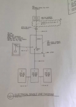
I was sent this afternoon a one line. Kinda interesting
I take it 400-4-1G means 4- 400 amp rated conductors and 1-G means one ground. Which tells me is a installers choice. For the two 3/0 on the Fedder from transfer 400 amp main breaker to 400 amp ML panle,ok. The EGC sizing is incorrect as they used #4 in each raceway. Which should be #3.
The one line showed what I do believe is an GEC and required by the city of Tulsa which there is none in the service disconnect (service rated transfer switch). Utility and load reversed at there respective termination points.
The one line showed a nema 1, I do believe this sets outside. I will confirm.
One line shows an 1/0 ground from utility transformer to the meter and the transfer switch. This is not a feeder set up. It is a utility feed. The power company here does not allow this. They used to years back from what I'm told and since said no way. Also in the pic there no EGC on the utility side as shown on one line.
Since the ran 500 mcm and used the round up rule the one line shows 400 not 380, unknown connected load. Maybe should have ran 600 mcm cu. However with a 125 KVA generator I would think 500 would be ok.
Just another day in or industry.
I take it 400-4-1G means 4- 400 amp rated conductors and 1-G means one ground. Which tells me is a installers choice. For the two 3/0 on the Fedder from transfer 400 amp main breaker to 400 amp ML panle,ok. The EGC sizing is incorrect as they used #4 in each raceway. Which should be #3.
The one line showed what I do believe is an GEC and required by the city of Tulsa which there is none in the service disconnect (service rated transfer switch). Utility and load reversed at there respective termination points.
The one line showed a nema 1, I do believe this sets outside.
I will confirm.One line shows an 1/0 ground from utility transformer to the meter and the transfer switch
. This is not a feeder set up. It is a utility feed. The power company here does not allow this. They used to years back from what I'm told and since said no way. Also in the pic there no EGC on the utility side as shown on one line.Since the ran 500 mcm and used the round up rule the one line shows 400 not 380, unknown connected load. Maybe should have ran 600 mcm cu. However with a 125 KVA generator I would think 500 would be ok.
Just another day in or industry.
Attachments
Tulsa Electrician
Senior Member
- Location
- Tulsa
- Occupation
- Electrician
I have to add this.
Just found out this install has no GEC at meter or service disc. No ground rods no nothing. The j man said he has two EGC in the feeder and that is all that is required.
And there is no 1/0 ground as shown on one line from trans. Well he got one thing right.
The part that boggles mind is it passed inspection and they set the meter. What he thought was #4 was is #6 for the feeders EGC
The power company requires a secondary insp for all transfer switch that could back feed utility.
So three people dropped the ball.
Wow.
Good thing the apprentice was paying attention and called the boss.
Fred B
Senior Member
- Location
- Upstate, NY
- Occupation
- Electrician
Was this one of those, "My Inspector friend gave me a sticker" situations?
At least it was caught before someone got hurt. Keep that apprentice.
At least it was caught before someone got hurt. Keep that apprentice.
Darned straight! The apprentices who ask probing questions and won't let go until they understand what is going on are pure gold!Keep that apprentice.
Tom Horne
Tulsa Electrician
Senior Member
- Location
- Tulsa
- Occupation
- Electrician
Even though he works else where he is still under my wing. If I choose to train one it's for life. It was a proud day for me. He remembered his training. If it don't look right, say something. And don't back down if it a safety issue.
As far as inspection goes his boss was not happy.
Wonder what the state insp would think. In Oklahoma it is the CIB.
Wonder what the power company safety inspector would think
Some one could loose the job for this one. Possible back feed during an Outage. How some one did the paper work
Pretty sure the system would not transfer. Don't know with out seeing specs. It's a 125 kva so it may just run up and transfer under utility voltage drop.
He is getting me model # and pdf.
Pretty sure his boss is taking corrective action so I will see what takes place.
Then there's the factory generator tech that has to sign off. So this would be the last fail safe for the install.
Why does it bother me when ladder diagrams, line diagrams, and schematics show the armature of a relay, or any other switch for that matter, on the wrong side of the contact? I don't know but it always does.
As to inspectors the kinds of things that they overlook and the corrections they ask for when they encounter real problems sometimes boggle my mind. In one hotel I worked on, as the Fire Alarm and Control integration technician, There was no neutral pulled from a wye connected transformer to the service equipment rated fire pump controller AND no neutral pulled from the Wye connected Emergency Generator to the transfer switch supplying wye connected loads. The fire pump motor was delta wired and didn't care a jot but the US NEC still requires a reduced size neutral as a low impedance fault current pathway from any transformer which has a grounded tap in the secondary windings. What that generator will do when there is a prolonged outage rather than it's unloaded weekly test is out of my theoretical depth but I imagine that will have a lot to do with how heavily it is actually loaded. The imbalance current which would normally flow in the absent neutral will probably flow over the Grounding Electrode Conductors or the generator and the general service equipment and through the main bonding jumper of the main service and back to the transformer under normal operation and take a similar route back to the generators windings neutral point under generator power. If there is a hole in that guesswork please let me know. I still love learning more about electricity even at 72 YOA.
Tom Horne
- Status
- Not open for further replies.