L
Lxnxjxhx
Guest
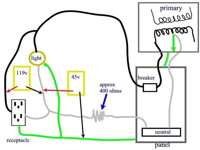
480/277 delta primary to a 120/208 volt wye secondary
480/277 delta primary to a 120/208 volt wye secondary
Thanks for the info.
"i think the maintanence department likes to play electrician"
Fine, let'em fix it. They can have the credit as long as they take the risks.
480/277 delta primary to a 120/208 volt wye secondary
Thanks for the info.
"i think the maintanence department likes to play electrician"
Fine, let'em fix it. They can have the credit as long as they take the risks.