mbrooke
Batteries Included
- Location
- United States
- Occupation
- Technician
Your on the money, but I have no idea like you if it will work or if the left transformer needs to be of a special variety.
Four lead XFs are readily available. It just brings the internal bond to the outside.
I know, but a standard 4 x?
We have a couple of them installed on our system.
we call them bastard banks.
they work OK but not for big loads.
some things to remember with this bank..
kVA is 3/4 of nameplate
0 degree leg is 1/2 kVA of first pot
120 degree leg is 1/2 kVA of the other pot
and the other leg is 1/2 of the smallest pot. The voltage drop is two times normal VD, and the losses are doubled
Yes, we have a yard full of them
What is the advantgage of using them? Advantage of a real wye system is ability to balance things.
Advantage of open delta is less primary conductors and infrastructure to what is usually a limited load and still have three phase secondary.
If you absolutely need 208 volts for a particular load then why not use a buck/boost transformer for that load?
bottom line is cost. It was cheaper to pull three wires instead of four when it was originally built.
we won’t do it now.
Why don't POCOs just pull 3 wires and connect everything phase to phase?
Those comments apply only to the C phase created with 2 secondary windings, I assume?some things to remember with this bank..
The voltage drop is two times normal VD, and the losses are doubled
And no neutral, even for grounding purposes?:jawdrop:
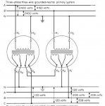
In the schematic that you posted above the A and B outputs are of course produced by 2/3 of the normal wye-wye transformer connection.
Phase C is being synthesized at the transformer secondaries just like in my post at the following link:
https://forums.mikeholt.com/forum/a...ng/2546600-1-ph-to-3-ph-converter#post2546705
In your schematic, the necessary inverted versions of A-N and B-N are produced by the reverse polarity connections of X4,X3 and X3,X2 respectively.
We have one built that feeds one small motor for hvac at a camp. It’s back in the woods about 6 miles. We have Vee phase (two lines of three phase) in there now, it’s been that way for years.
bottom line is cost. It was cheaper to pull three wires instead of four when it was originally built.
we won’t do it now.
BTW, that line is due for upgrades. When we reconductor it we will pull in new three phase and new neutral.
the good thing here is the camp can shut down for three weeks so we can do this dead. More savings. This help drive our decision to include the fourth wire and retire this particular bank.
the rest will be retired eventually. I think we have four not counting this one.
We have lots of limited loads both along the main lines and in isolated areas. If three phase is needed open delta is what is used. What is the advantage of this particular setup over the open delta?
Small motors probably get phase conversion equipment in isolated areas with single phase only being what is readily available from POCO.
120/208
like I say, we wouldn’t build it now as most motors now are 208/230
In the schematic that you posted above the A and B outputs are of course produced by 2/3 of the normal wye-wye transformer connection.
Phase C is being synthesized at the transformer secondaries just like in my post at the following link:
https://forums.mikeholt.com/forum/a...ng/2546600-1-ph-to-3-ph-converter#post2546705
In your schematic, the necessary inverted versions of A-N and B-N are produced by the reverse polarity connections of X4,X3 and X3,X2 respectively.