Let's give it a try, even though it will duplicate what Larry said to a great extent:
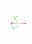
The phasors in Hv&Lv's diagram below represent the voltages across each secondary winding on the two transformers. The origin and the tip of each phasor corresponds to the terminals at the end of each secondary winding. The red phasors are from one transformer, and the green ones from the other. Note that each transformer can only produce a phasor in one direction in the complex plane (or its 180 degree opposite just by reversing the winding polarity). The transformers are operating 120 degress from eachother but we need a third phase. Where the origin (i.e., starting point) of the phasor is located is determined by where the corresponding end of the winding is connected in the circuit.
Phasors and corresponding secondary windings:
second transformer
X
2 connected to N
red phasor #1: X
2 to X
1
red phasor -#1: X
2 to X
3 (reverse polarity of #1)
first transformer
X
2 connected to N
green phasor #3: X
2 to X
1
green phasor -#3: X
3 to X
4 (reverse polarity of #3)
So origin of red phasor -#1 is the neutral
The origin of green phasor -#3 is the end of red phasor -#1 because of the connection between the X3's of each transformer. Basically, green phasor -#3 is added to red -#1 because its corresponding winding is in series with that of -#1. The sum of these two phasors creates a new phasor referenced to N which is blue #2 on HV&Lv's diagram. Phasors -#1 and -#3 form an open delta, where one end of the open delta is connected to neutral (at the origin of -#1) and the other end creates the new blue #2 phasor, which goes from neutral to the end of the -#3 phasor.
Green phasor #3 and red phasor #1 are of course the two phases of the wye output coming directly from each transformer. Therefore blue #2 completes all three output phases of the wye.
I hope that was wordy enough
")