Isolated ground

Status
Not open for further replies.
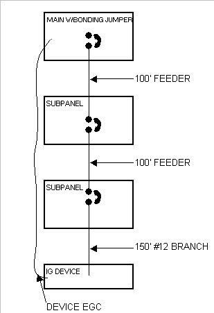
Here?s a visual of a likely scenario. This is why I have trouble accepting isolated ground circuits.
IGCircuitScenario.jpg
 
Bob,
The isolated grounding conductor could be a lot longer than the associated branch circuit conductors in the cases where the system bonding jumper or main bonding jumper is not in the same panel as the branch circuit OCPD.

Don,

Yes of course it could be, but consider these two situations

1) You have an SDS with the panel located right beside it.

Branch circuit 1 is a 20 amp 120 volt 'normal' circuit 200' one way from panel wired with 12 AWG.

The NEC allows this and says nothing specifically about increasing the EGC due to length.

2) You have SDS with 175' from transformer to panel.

Branch circuit 1 is a 20 amp 120 volt 'IG' circuit 25' one way from panel wired with 12 AWG.

The NEC allows this and says nothing specifically about increasing the IEGC due to length.

Electrically both circuits have close to the same ground fault impedance. So I stand by my earlier statement that the IGC is really no different than EGC


I don't think the code directly addresses the sizing of the isolated grounding conductor in this case.

I agree but will add it does an equally poor job with a normal EGC.

I am still trying to figure out how 250.122(B) can effect this, it is really not clear.:-?
 
The NEC does not directly address IG circuits because these are not exempt of the requirements of 250.118 & 250.122. The isolated ground circuit is still equipment grounding (only more important it is it?s the equipments only ground fault path).

If equipment manufactures require ground reference it is by their mistake, this is a poor reason to cause hay-wiring of something as important as fault path.

The example I posted may or may not have an overhead served/supplied main but it is the most common in California. Think about existing situations where new equipment is listed needing these lame requirements and how your going to route the IG.

In my example even if the isolated ground terminates at the main it will need to route beyond its respective phase conductors by over 200?. It will also require additional conduit this additional distance or be installed through two subpanels with feeders [UGH].
 
If equipment manufactures require ground reference it is by their mistake, this is a poor reason to cause hay-wiring of something as important as fault path.

They are not bond by the NEC and all data equipment that uses RS-232 type interconnections still use a ground reference.

The example I posted may or may not have an overhead served/supplied main but it is the most common in California.

I find that hard to believe, your drawing indicates that the IG runs all the back to the utility transformer.

How exactly would that be done?

The IG should be run back toward the source and stop at the first point of intentional neutral bonding. In a building without any SDS this point will be the service disocnect enclosure.


Think about existing situations where new equipment is listed needing these lame requirements and how your going to route the IG.

In an existing installation your best bet would to make the branch circuit run back to the main panel or back to the first panel on the load side of an SDS. Or run a new feeder from there as you will never be able to sneak an IG in with existing feeders.

In my example even if the isolated ground terminates at the main it will need to route beyond its respective phase conductors by over 200’.

Yes, I agree, and there is nothing to prevent that in the NEC or having a 200' long branch circuit with a standard size EGC.


It will also require additional conduit this additional distance or be installed through two subpanels with feeders .

You lost me, the IG will be run in the same conduit with the feeders, there is no option to run it outside those raceways.
 
They are not bond by the NEC and all data equipment that uses RS-232 type interconnections still use a ground reference.

We are bound though, and this is my point we need to still install correctly.

I find that hard to believe, your drawing indicates that the IG runs all the back to the utility transformer.

How exactly would that be done?

My point exactly! This drawing reflects what you said in a previous post regarding terminating at the supply XO. Otherwise the example is highly likely (and most common) with multiple panels before branching.

The IG should be run back toward the source and stop at the first point of intentional neutral bonding. In a building without any SDS this point will be the service disocnect enclosure.

Again this is most commonly multiple panels away.

In an existing installation your best bet would to make the branch circuit run back to the main panel or back to the first panel on the load side of an SDS. Or run a new feeder from there as you will never be able to sneak an IG in with existing feeders.

Also my point exactly! Applications like these force bizarre installations. Also these type applications should most often cause 250.122(B) to take affect for voltage drop because of lengths.

You lost me, the IG will be run in the same conduit with the feeders, there is no option to run it outside those raceways.

If your branch originates at the last subpanel you have to find a way to get your IG to your bonding point, as you now say is at the main in my example. :)

I am only trying to point out how convoluted these circuits quickly become. Yet THE purpose remains; to provide an effective ground fault path, rather then the duel purpose of signaling ground reference and fault path. :)
 
...
I agree but will add it does an equally poor job with a normal EGC.

I am still trying to figure out how 250.122(B) can effect this, it is really not clear.:-?
I don't see any 250.122(B) issues here. You could use the performance requirements in 250.4, backed by calculations to require larger EGC conductors for either a normal or isolated EGC.
 
My point exactly! This drawing reflects what you said in a previous post regarding terminating at the supply XO. Otherwise the example is highly likely (and most common) with multiple panels before branching.
You would only run the isolated EGC to XO where the system is SDS and the system bonding jumper is installed at the transformer.
Also my point exactly! Applications like these force bizarre installations. Also these type applications should most often cause 250.122(B) to take affect for voltage drop because of lengths.
While I agree that the long isolated EGC should be increased in size, I don't see how 250.122(B) applies as the branch circuit conductors for this circuit have not been increased in size and increasing the size of those conductors is the only thing that triggers the application of 250.122(B).
If your branch originates at the last subpanel you have to find a way to get your IG to your bonding point, as you now say is at the main in my example. :)
The only code permitted path for the IG conductor is the raceway or cable that contains the feeder conductors for all of the panels between the main or system bonding jumper and the panel that supplies the IG circuit.
 
My point exactly! This drawing reflects what you said in a previous post regarding terminating at the supply XO. Otherwise the example is highly likely (and most common) with multiple panels before branching.

No, not at all, I said it goes back to the XO of an SDS and I certainly did not mean by a route outside the conduits or cables.
 
No, not at all, I said it goes back to the XO of an SDS and I certainly did not mean by a route outside the conduits or cables.

I know you didn't, I just meant if this IG does not travel with the feeders there's no other way. Pulling it with [or adding it to] feeders is really the only compliant option, and a poor one at that. :roll:
 
...While I agree that the long isolated EGC should be increased in size, I don't see how 250.122(B) applies as the branch circuit conductors for this circuit have not been increased in size and increasing the size of those conductors is the only thing that triggers the application of 250.122(B).

I agree and I believe we're saying the same thing. I said this in light of as if the branch originates from the same termination point as the IG (at the main). If the branch did it would be over 350' long and require upsizing the CCC's and the application of 250.122(B).

But because the branch terminates at the last panel the IG (EGC) is no longer a problem with VD even though it remains over 350' long (over 200' longer than its circuit conductors); kool :cool:...what-ever :-?

This just seem's inconsistant. Hay-wire :roll:
 
...The only code permitted path for the IG conductor is the raceway or cable that contains the feeder conductors for all of the panels between the main or system bonding jumper and the panel that supplies the IG circuit.

Don, as you say here will the IG still be ?running with? its circuit conductors, just ahead of [or beyond] the actual 20A circuit breaker? This is where I say the IG is not running with its circuit because I understand the feeders as different circuits, is this correct?

This point really matters especially in existing installations the bonding point may/may not have distribution possibly causing the 20A circuit breaker to be downstream while its IG is fished through an existing feeder conduit, (could be #12 with 4/0? or 400?s?[UGH no matter what]).
 
I do see now 250.122(B) is just not likely because if I look at an example of 200 watts its circuit can run over 900? before causing >3% VD. So the other option of starting the 20A circuit at a main with distribution is more graceful.

I do understand why 250.122(B) is used for VD; I just see it as inconsistent if not applied to an IG that is extremely long like the one above.
 
Status
Not open for further replies.
Top