Yes, but the client had brought this transformer. And when they talked with Larson, all they said was is that they could provide an isolation transformer for what they needed. I don’t think they realized they needed a grounded neutral for the system. As expressed above, it is really just 2 hot making a single circuit making 230 volt line to line.The manufacturers description of the transformer is a little off from the diagram and seems odd to me;
'L+L+N' to me suggests a 3 wire primary side. and the 'L' + 'N' on the secondary suggest that N is already bonded to the case. If not I would think it would have X1 and X2.
Based on the diagram (assuming its correct) I would think it should say something like "the MT-ISX-FP-1P-208V-5KVA-220V.EU-N3R-50HZ isolation transformer is a single phase unit with a primary voltage of 208 V Single Phase. It also provides a secondary voltage of grounded 230 V single phase where N is bonded to the case.."
You are using an out of date browser. It may not display this or other websites correctly.
You should upgrade or use an alternative browser.
You should upgrade or use an alternative browser.
Isolation transformer
- Thread starter Cursitti
- Start date
- Location
- New Jersey
- Occupation
- Journeyman Electrician (retired)
Actually the output should be 220 volts according to the nameplate. Can you draw a sketch showing the installation with all of the connections to the primary, secondary, GEC, EGC, system bonding jumper?Yes, but the client had brought this transformer. And when they talked with Larson, all they said was is that they could provide an isolation transformer for what they needed. I don’t think they realized they needed a grounded neutral for the system. As expressed above, it is really just 2 hot making a single circuit making 230 volt line to line.
I'd be curious to see if there is continuity between N and the transformer case.Yes, but the client had brought this transformer. And when they talked with Larson, all they said was is that they could provide an isolation transformer for what they needed. I don’t think they realized they needed a grounded neutral for the system. As expressed above, it is really just 2 hot making a single circuit making 230 volt line to line.
Calling something a 'European' voltage is kinda a misnomer while they agreed on a standard voltage and frequency the grounding salad (Earthing Systems) in Europe are anything but simple.
While 400Y230 is most common in urban areas, villages and towns, you can find areas that have a 230V corner grounded delta (Norway), 220Y127 (Spain), 230/460 single phase, even 230V ungrounded you can have just about any type of grounding (earthing) you can think of.
And since the UK just standardized on paper but never changed anything they are effectively 240V.
Last edited:
I can draw you a pic tonight when I get home. It says 220 on that transformer and on the other it says 230 on both I’m getting 230. I connected my primary lines to H1 and H3. H1 &H4 are capped. And the secondary side is self explanatory. I will draw how i did the grounding and bonding with the neutral. I couldn’t do all of this inside the transformer as there isn’t a lot of room so i had to result in landing the neutrals on the disconnect bar and screwing the bonding screw and landing a jumper between my grounds to the bar.Actually the output should be 220 volts according to the nameplate. Can you draw a sketch showing the installation with all of the connections to the primary, secondary, GEC, EGC, system bonding jumper?
Believ me I’m curious too. I’m still waiting on the client to give me an answer. No news is goood news but in my mind i want this to be right. And i want to figure this out for future referenceI'd be curious to see if there is continuity between N and the transformer case.
Calling something a 'European' voltage is kinda a misnomer while they agreed on a standard voltage and frequency the grounding salad (Earthing Systems) in Europe are anything but simple.
While 400Y230 is most common in urban areas, villages and towns, you can find areas that have a 230V corner grounded delta (Norway), 220Y127 (Spain), 230/460 single phase, even 230V ungrounded you can have just about any type of grounding (earthing) you can think of.
And since the UK just standardized on paper but never changed anything they are effectively 240V.
Tulsa Electrician
Senior Member
- Location
- Tulsa
- Occupation
- Electrician
That should be easy to check.. It also provides a secondary voltage of grounded 230 V single phase where N is bonded to the case.."
In the future I would question if that thing is needed, I would wager most any recent 230V 50/60 hz rated equipment from overseas will run fine here Line - Line without any transformer. Tolerance is +/- 10% of 230V, so a 208 that typically runs a little high like 217 is well within their IEC spec. If you really need isolation then no-matter what you need a transformer though.And i want to figure this out for future reference
Tulsa Electrician
Senior Member
- Location
- Tulsa
- Occupation
- Electrician
Let's call it a (N) connection. Once grounded it's a grounded conductor. Simple sieres circuit. You have no netural tap point between (L) and (N).I can draw you a pic tonight when I get home. It says 220 on that transformer and on the other it says 230 on both I’m getting 230. I connected my primary lines to H1 and H3. H1 &H4 are capped. And the secondary side is self explanatory. I will draw how i did the grounding and bonding with the neutral. I couldn’t do all of this inside the transformer as there isn’t a lot of room so i had to result in landing the neutrals on the disconnect bar and screwing the bonding screw and landing a jumper between my grounds to the bar.
I would make sure (N) is grounded to case or not first as others have mentioned.
The diagram does not show (N) grounded.
Once you ground (N) than it's a grounded conductor.
Look forward to your diagram.
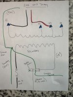
Attached is the wiring diagram. As stated before I couldn’t get a good bond to case and put a lug and a bunch of ring terminals on the grounds post inside the transformer. So i took my grounds and electrode to the disconnect which is located right below transformer and put neutrals and ground on terminal and used screw to enclosure. Also with the transformers off i was stilll getting current on my electrode dude to the RF guys using my ground bar and grounding there chamber and filters. It wasn’t until i shut off all circuits the current went away.Let's call it a (N) connection. Once grounded it's a grounded conductor. Simple sieres circuit. You have no netural tap point between (L) and (N).
I would make sure (N) is grounded to case or not first as others have mentioned.
The diagram does not show (N) grounded.
Once you ground (N) than it's a grounded conductor.
Look forward to your diagram.
It got worse when i turned the secondary disconnect on but with the secondary disconnect off it stayed the same.
Attachments
winnie
Senior Member
- Location
- Springfield, MA, USA
- Occupation
- Electric motor research
Also with the transformers off i was stilll getting current on my electrode dude to the RF guys using my ground bar and grounding there chamber and filters. It wasn’t until i shut off all circuits the current went away.
It got worse when i turned the secondary disconnect on but with the secondary disconnect off it stayed the same.
Your diagram looks reasonable to me. Your transformer grounding as drawn shouldn't be injecting current into the GEC.
The line about 'with the secondary disconnect off it stayed the same.' is intriguing, and suggests that the source of the current is external to the transformer.
Sadly I don't have any hunches.
ELA
Senior Member
- Occupation
- Electrical Test Engineer
Sounds like interactions between two different power sources? Your new 230V circuit and 2 existing 120V -20amp circuits?I have found that with 2 single phase 20 amp circuits they are using in the chamber that when they are on I am getting about .35 amps on the GEC. This is just a standard 20 amp plug on the inside of the RF chamber that goes through a filter. It gets worse when I turn on both transformers and turn on the secondary disconnects.
When you connect the ground the interaction produces the undesired current. Especially when 120V loads are turned on!
Is there a chance you might need a Isolation transformer with a center tapped secondary where you then ground the center tap for symmetry?
To totally understand what is happening a circuit diagram detailing both sources of power and their interconnections is required.
So you have two ground wires to the transformer a supply side bonding jumper (SSBJ) and a equipment ground?
The only logical explanation for the objectionable current is there is a parallel neutral path from the 230V neutral / ground bar in the disconnect
back to the transformer, and that makes me suspect a factory N-G bond, In which case you would of course float the neutral in the disco.
I would disconnect the all the leads from the transformer and verify there is not a hidden factory N-G bond.
Also not that it make a huge difference but I would move your wire labeled 'equipment ground' going to the 230V loads from the transformer to the ground bar at the disconnect like so;

Haven’t been back and i doubt they are going to call me back. Right now the system is ungrounded and I’m assuming their testing went fine. As we do a lot of work for this client and if something wasn’t right they would have called. I told the client i would like to come back and ground it and find out where the current is coming from. The problem has to be that chamber or the filters. Because the 20 amp circuits will have current on the grounds even with the transformers off. It just gets worse with them on. I also doubt a factory bond because I wouldn’t be reading 120 on the neutral if it was bonded inside. Factory directions say they bond the case to the core nothing about the windings.This is what I would probably do;
View attachment 2576853
This situation has ate me up and id like to fix it and know why this is happening but i guess ill never know unless I’m called back to investigate.. but as long as the client is happy and their equipment is working as it should they probably wont call. As of now the white and black secondary wires are connected to individual poles and the secondary disconnect infused. I know if one conductor became grounded. It should be safe and there shouldn’t be no shock hazard. But I wanted to fuse just in case both touched and it would Blow a fuse. But I can’t do anything about it now as I have expressed my concern to the client.
Ahh thats right I forgot that, must be the equipment then,I also doubt a factory bond because I wouldn’t be reading 120 on the neutral if it was bonded inside.
Is it old equipment? I have seen leaky power supply caps in old equipment dry out and start to leak and completely short to equipment ground.
All this equipment is apparently new. They flew in a special contractor to install this chamber. As it needs to be filtered power and a basically fair a cage. From my understanding, the RF that they are shooting in the chamber can take down an airplane. I checked neutral to ground post in the filters and it didn’t seem like they were bonded together. But they did come from overseas, so who knows what kind of shape they’re inAhh thats right I forgot that, must be the equipment then,
Is it old equipment? I have seen leaky power supply caps in old equipment dry out and start to leak and completely short to equipment ground.