Julian

Status
Not open for further replies.
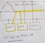
Can you please show me the math for calculating the minimum standard size fuse required to protect the conductor for Phase-B in the feeder, given a 3-Phase, 3-Wire 480 V Delta (no neutral). The three line-to-line loads are 49 kW single-phase for each of the three loads (Load_1 is 49 kW Line B-C, Load_1 is 49 kW Line A-B, Load_1 is 49 kW Line A-C). Your help would be greatly appreciated.
Julian
 

Attachments

  • Three Phase Three Wire Delta question.jpg
    Three Phase Three Wire Delta question.jpg
    56.8 KB · Views: 0

augie47

Moderator
Staff member
Location
Tennessee
Occupation
State Electrical Inspector (Retired)
Been too many years since college & computers have ruined me..:)
My computer, if it can be trusted, shows the load to be 178 amps, next standard size fuse would be 200 amps.
I'll let one of the young 'uns show you the math(.and check me) :)
 

__dan

Senior Member
Load Amps are 102. 49 kW / 480 Volts. B feeder could be 204 Amps if the fuse is between the transformer and the load bus or tap point.

Fuse size per code depends on the load type.. Sized to protect the conductor, except for motor loads, which allow increased fuse size to carry motor starting current.

Select the conductor size for the load, then select the fuse size to protect the conductor installed.
 
Last edited:

Jraef

Moderator, OTD
Staff member
Location
San Francisco Bay Area, CA, USA
Occupation
Electrical Engineer
What are the loads? Heating? If so, and they are resistance heaters, then 49,000/480V = 102A, conductor sized for 125% = 128A, you could fuse it at 130A using 1AWG conductors or even make a case for 150A using 1/0 conductors (although as non-continuous you could preclude all of that and fuse it at 110A and run #2), but we know nothing about your distances and conduit fills etc.

Bottom line I think maybe you are over thinking this because it is a delta source and that has you thinking there is something special here. It's not, you just have 3 separate single phase 49kW 480V loads, each one is stand-alone from a fusing and conductor sizing standpoint.
 

mivey

Senior Member
I'm with augie47: 176.81 amps.

147 kW load. 147 ÷ sqrt(3) ÷ 0.480 = 176.81 amps of load leaving the transformer via the feeder.
 
I am not using a computer to calculate and do not understand where this formula comes from ... 147 kW load. 147 ÷ sqrt(3) ÷ 0.480 = 176.81 amps.

I was thinking since the diagram does not indicate what type of load, would it simply be the load per phase is 49,000/480V = 102 amps, then fuse at next higher standard size of 110 amps per 240.6. My options are 60, 110, 125, 200 amps.
 

__dan

Senior Member
If the loads were Y connected, I am seeing 277 V through the load and 176.9 Amps for the B leg.

Delta connected loads shown, I'm seeing 480 V across the load and 102 Amps. But there are two of them on the B phase for 204 Amps. 3/0 copper and 225 Amp fuses come to mind
 
If the loads were Y connected, I am seeing 277 V through the load and 176.9 Amps for the B leg.

Delta connected loads shown, I'm seeing 480 V across the load and 102 Amps. But there are two of them on the B phase for 204 Amps. 3/0 copper and 225 Amp fuses come to mind

but with three balanced loads as shown , each supply line sees 1.73 times the individual load current not twice.
 
It is a Delta system, and two of the loads use Phase B, each at 49 kW. So, I first thought 204A, but can you size down to 200 A for the OCP?
I seem to remember that feeder OCP is the only time you should size down, but is there an NEC article that states this clearly, or simply a rule of thumb?
 

__dan

Senior Member
but with three balanced loads as shown , each supply line sees 1.73 times the individual load current not twice.

I've been drawing out the circuits trying to see where the change in the load amps happens. I am very familiar with the 1.73 factor for three phase power. I'm seeing the B phase node at 102 + 102 = 204. I would have to hook it up and meter it to see if the delta load connection is going to give me 102 + 102 = 176.9.

Still trying to resolve the difference.
 

__dan

Senior Member
It is a Delta system, and two of the loads use Phase B, each at 49 kW. So, I first thought 204A, but can you size down to 200 A for the OCP?
I seem to remember that feeder OCP is the only time you should size down, but is there an NEC article that states this clearly, or simply a rule of thumb?

You would have to select a conductor size suitable for the load. When you find the specific reference, I'm sure it does not allow undersizing from the calculated number. Calculating the load amps takes into account pro and de rating.

So next larger wire size from the table, then a (next larger) fuse size to protect the conductor. For the non continuous load, you can load to 100% of the fuse and conductor size.
 
So question,
1. Load per phase is 49,000/480V = 102 amps,
2. Since there are three balanced loads, each supply line sees 1.73 times the individual load current (not twice), so 102 amps x 1.732 = 176.81 amps,
3. Now, do you fuse at next higher or lower standard size per 240.6 for this feeder OCP???
Y'all are a big help :))
 

gar

Senior Member
Location
Ann Arbor, Michigan
Occupation
EE
190103-2035 EST

julian padilla:

Your question as posted is not real clear to me.

First, assume all the loads are resistive.

Then the question is what wires are to be fused?

If you assume each load is to be fused individually, then clearly the current per load is 49,000 / 480 = 102.1 A.

If you want to fuse a leg from the delta transformer, which is what I think your question is, then you need vector addition of the two currents connected. The easy intuitive way to attack the problem is to convert the balanced delta load to a balanced wye load. No math needed. Just redrawing the load. Since the load is balanced and the source is balanced this means the center point of the star resistor network is at the same potential as the neutral point of a wye source used to replace the delta source. Thus, we now have a wye load connected to a wye source. All we need to know is the wye line to neutral voltage.

The wye voltage you probably know off the top of your hat, 480 / 1.732 = 277.1 V. Thus, line current from the transformer for a resistive load is 49,000 / 277.1 = 176.8 A. This is because the line to neutral voltage is in phase with the load current. If the power factor is not 1, then you need to do its correction.

.
 

don_resqcapt19

Moderator
Staff member
Location
Illinois
Occupation
retired electrician
So question,
1. Load per phase is 49,000/480V = 102 amps,
2. Since there are three balanced loads, each supply line sees 1.73 times the individual load current (not twice), so 102 amps x 1.732 = 176.81 amps,
3. Now, do you fuse at next higher or lower standard size per 240.6 for this feeder OCP???
Y'all are a big help :))
For a 176.81 non continuous load the minimum conductor size would be 3/0 and the maximum OCPD would be 200.
If the load is continuous, the minimum conductor size would be 4/0 and the maximum permitted OCPD would be 250 amps, rounded up from the 230 amp ampacity of the conductor to the next standard size OCPD which is 250 amps.
 

gar

Senior Member
Location
Ann Arbor, Michigan
Occupation
EE
190103-2355 EST

julian padilla:

Unbalanced no. Neither source voltage or load unbalance will will allow this approach. You need to use phasor (vector) analysis.

However, you can transform a delta load to an equivalent wye load, but the midpoint won't be a neutral point. The transform equations are provided at page 487 in "Basic Electrical Measutrements" by M. B. Stout, University of Michigan, Prentice-Hall, 1950.

.
 
Status
Not open for further replies.
Top