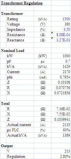
KVA and voltage drop

Status
Not open for further replies.

kwired

Electron manager
Location
NE Nebraska
This is not quite true, but is a good approximation to start with.

5% impedance means that with the secondary shorted, full current will flow with 5% voltage applied to the primary.

So in a very real sense, essentially 5% of the EMF has to be dropped across the transformer at full load.

But that is not a pure resistive drop; it has a large inductive component.

This means that the voltage seen by the load won't drop by the the full amount caused by the transformer impedance; some of it shows up as a change in phase angle. The voltage drop seen by the load also depends on the power factor of the load, and if the load is capacitive could also be seen as a voltage rise.

-Jon
Getting into an area I won't claim to be an expert on, but I do believe one also has to assume infinite supply capacity.
 

Besoeker

Senior Member
Location
UK
part of it is resistance.
Most of it is resistance - the inductive part causes volt drop but the inductances doesn't produce losses. For efficiency calculations, you need take into account iron losses. These are substantially fixed And some transformers have fan cooling and their power, though usually fairly low compared to the transformer rating, should be considered but often, in my experience, are not.
 

mivey

Senior Member
If the impedance of a transformer is 5%, does that mean that the efficiency is 95%?
Is it more likely to expect higher or lower efficiency, than (100%-impedance)?
It does not mean that. Impedance and efficiency are not the same thing just like volt drop and losses are not the same. The impedance is mostly reactance and only some resistance.

Are there any formulas to determine theoretical full load efficiency, knowing the impedance?
You can make some rough assumptions at best but the resistance and reactance ratios vary too much. To know for sure, you have to test the transformer for losses.
 

mivey

Senior Member
Most of it is resistance - the inductive part causes volt drop but the inductances doesn't produce losses. For efficiency calculations, you need take into account iron losses. These are substantially fixed And some transformers have fan cooling and their power, though usually fairly low compared to the transformer rating, should be considered but often, in my experience, are not.
Most of the impedance percentage is the reactive component. The resistive component that gives the losses and thus effects efficiency is a smaller component as most X/R ratios are much greater than one.
 

Besoeker

Senior Member
Location
UK
Most of the impedance percentage is the reactive component. The resistive component that gives the losses and thus effects efficiency is a smaller component as most X/R ratios are much greater than one.
The X shouldn't affect efficiency at all if it really is just X and that's how it's represented in the Steinmetz Equivalent Circuit.
 

winnie

Senior Member
Location
Springfield, MA, USA
Occupation
Electric motor research
Since the magnetizing inductance of a transformer is in parallel rather than in series with the reflected downstream impedance it seems to me that, as is the case with a motor, the idling current of a transformer has a large inductive component while the full load or fault load current of the same transformer has a relatively small inductive component.
That same factor applies to the voltage drop caused by the resistance of the secondary and primary windings, which together contribute to the %Z figure.

True for the magnetizing current.

But most transformers also have pretty significant 'leakage inductance' which is in series with the load and part of the transformer impedance.

Take a look at the Steinmetz which Beo mentioned.

-Jon
 

mivey

Senior Member
The X shouldn't affect efficiency at all if it really is just X and that's how it's represented in the Steinmetz Equivalent Circuit.
The %Z value has both X & R components. I know you know that so what is your direction?
 

mivey

Senior Member
True for the magnetizing current.

But most transformers also have pretty significant 'leakage inductance' which is in series with the load and part of the transformer impedance.

Take a look at the Steinmetz which Beo mentioned.

-Jon
and a series resistance as well.
 

Besoeker

Senior Member
Location
UK
The %Z value has both X & R components. I know you know that so what is your direction?
Yes, the Z value has X & R components. My point was about efficiency or losses which was brought up earlier in the thread.
 

mivey

Senior Member
Yes, the Z value has X & R components. My point was about efficiency or losses which was brought up earlier in the thread.
So back to that: some of the Z value has resistance and that component impacts the efficiency.


For very small transformers (say single-phase 10 kVA) we see an X/R ratio of maybe 0.4. For larger units we might see an X/R ratio of 5 to 10 or more.
 

Besoeker

Senior Member
Location
UK
So back to that: some of the Z value has resistance and that component impacts the efficiency.
Yes. The R component. Not the X. That was what I was getting at.

Here's a section of a spreadsheeet I did for a 2200 kW Kramer drive.

Losses
Chopper Amps (Adc) 125 187 262 352 456 574 707 856 1022
Max Chpr Amps (Adc) 1022
Chpr Chk Res (mohm) 11
Inverter Amps (Adc) 125 163 197 220 228 215 177 107 0
Max Invr Amps (Adc) 228
Invr Chk Res (mohm) 48
Max Rec reqired (kVA) 471
Rect/Ch loss (W) 675 1009 1417 1900 2461 3099 3819 4624 5520
DCC1 loss (W) 165 369 728 1310 2196 3484 5291 7758 11054
Inverter loss (W) 675 883 1063 1188 1230 1162 955 578 0
DCC2 loss (W) 752 1285 1862 2326 2495 2227 1503 551 0
Tx Fe loss (W) 3294 3294 3294 3294 3294 3294 3294 3294 3294
Tx Cu loss (W) 1418 2423 3511 4386 4705 4199 2834 1039 0
Fans (W) 500 500 500 500 500 500 500 500 500

Total Losses (kW) 7.5 9.8 12.4 14.9 16.9 18.0 18.2 18.3 20.4
Output (kW) 85 165 284 449 669 950 1301 1730 2244
Shaft Power (kW) 85 165 284 449 669 950 1301 1730 2244
Speed (rpm) 500 624 747 871 995 1118 1242 1365 1489
Torque (pu) 0.11 0.18 0.25 0.34 0.45 0.56 0.70 0.84 1.00

Efficiencies
ISK efficiency (%) 90.8% 93.6% 95.2% 96.3% 97.2% 97.9% 98.4% 98.8% 99.0%
Motor efficiency (%) 91.3% 93.3% 94.5% 95.3% 95.7% 96.0% 96.1% 96.2% 96.1%
Mechanical output (kW) 85.0 164.9 283.6 449.0 668.6 950.2 1301.5 1730.2 2244.0
Rotor Power (kW) 190.1 248.5 299.8 336.1 349.6 332.3 276.4 174.7 20.4
Stator Power (kW) 301.4 443.2 617.4 824.1 1063.5 1335.7 1641.2 1980.9 2356.6
ISK Output (kW) 182.6 238.7 287.4 321.2 332.7 314.3 258.2 156.3 0.0
ISK Losses (kW) 7.5 9.8 12.4 14.9 16.9 18.0 18.2 18.3 20.4
Motor Losses (kW) 26.3 29.8 34.0 39.1 45.4 53.3 63.3 76.0 92.2
Total Losses (kW) 33.8 39.6 46.4 54.0 62.2 71.3 81.5 94.4 112.6
Efficiency (%) 71.6% 80.6% 86.0% 89.3% 91.5% 93.0% 94.1% 94.8% 95.2%

They don't paste altogether correctly on forums but all the numbers are there. And it's a real application in operation in a cement works.
 

junkhound

Senior Member
Location
Renton, WA
Occupation
EE, power electronics specialty
parsed and pasted as picture nice information on chart, esp as a real life example.

somewhat surprised that the core losses (Fe loss) stays constant.

boes.jpg
 

Besoeker

Senior Member
Location
UK
Brilliant job!
Thank you so much, JH!
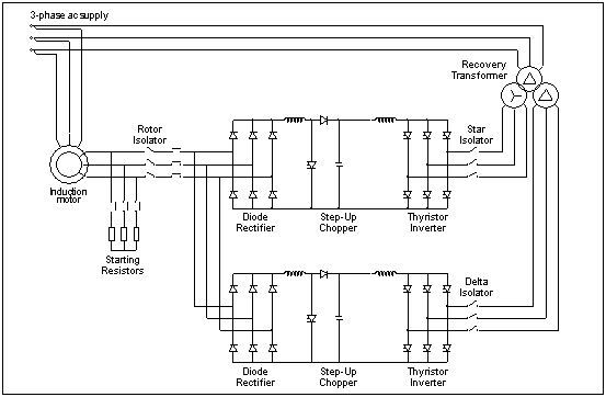
FWIW, this a simplified version of the circuit arrangement:

ISK02_zps581cb828.jpg
 
Status
Not open for further replies.
Top