load-side tap headache

Status
Not open for further replies.

deadshort

Member
Location
Nor Cal
Hi guys, I know this subject has been beat to death but we are up against the wall with this plans checker.

We are planning on making a load side tap into #2 Service entrance cable feeders (not the bussing) which is protected on the utility side by a 100A main and at a sub panel by an additional 100A main.

We will be installing a 60A fused disconnect before the tap. The SER cable is rated for 100A. The max output of the inverter is 47.5A (with 125% needs the 60A fused disco).

Question: How could we possibly overload this feeder if it is rated for 100A and the loads are protected by a 100A breaker as well as the 100A breaker in the main?

The plans checker keeps referring to NEC 705.12(D)(2): " The sum of the ampere ratings of overcurrent protection devices in circuits supplying power to a busbar or conductor shall not exceed 120 percent of the rating of the busbar or conductor."

He is saying we are limited to 20A. When I pointed out the existing OCPD and asked how we could possibly overload the feeders he just kept repeating the code back to me and is not open to logical discussion.

How can we win this argument?

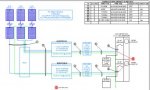
I've attached a oneline for clarification.
 

Attachments

  • ONELINE.jpg
    ONELINE.jpg
    25.9 KB · Views: 0
Hi guys, I know this subject has been beat to death but we are up against the wall with this plans checker.

We are planning on making a load side tap into #2 Service entrance cable feeders (not the bussing) which is protected on the utility side by a 100A main and at a sub panel by an additional 100A main.

We will be installing a 60A fused disconnect before the tap. The SER cable is rated for 100A. The max output of the inverter is 47.5A (with 125% needs the 60A fused disco).

Question: How could we possibly overload this feeder if it is rated for 100A and the loads are protected by a 100A breaker as well as the 100A breaker in the main?

The plans checker keeps referring to NEC 705.12(D)(2): " The sum of the ampere ratings of overcurrent protection devices in circuits supplying power to a busbar or conductor shall not exceed 120 percent of the rating of the busbar or conductor."

He is saying we are limited to 20A. When I pointed out the existing OCPD and asked how we could possibly overload the feeders he just kept repeating the code back to me and is not open to logical discussion.

How can we win this argument?
I don't know that you can since he is going by the 2011 NEC. The "or conductor" was taken out of the 2014 code, and some AHJ's were willing to overlook it prior to that, but if the planner is sticking to this language you may be SOL.
 
I don't know that you can since he is going by the 2011 NEC. The "or conductor" was taken out of the 2014 code, and some AHJ's were willing to overlook it prior to that, but if the planner is sticking to this language you may be SOL.

Thanks Gunn. Kinda what I figured. Back to the drawing board...
 
Thanks Gunn. Kinda what I figured. Back to the drawing board...
As I understand it, the 2014 NEC has been adopted over there in CA, and will go into effect 1/1/2017. Not the desired solution, but given there is no easy solution, perhaps put the project on the backburner until then.
 
Random uninformed idea: is there any way to use the feeder tap rules to help with the issue of 2011 705.12(D)(2)? Because that's effectively what's going on in the proposed interconnection, the #2 conductors aren't being protected from overload at its point(s) of supply. The proposed arrangement depends on the load end 100A breaker for overload protection.

Cheers, Wayne
I most view 705.12(D)(2) as superseding 240.21(B) per 90.3.
 
So I think we've found a solution. Going to add a new 200A sub panel , replace the 100A main in the meter panel with a 175A sub feed (allowing 65A of PV in the new sub) and relocate the 100A that was in the meter main to the sub which will in turn feed the remote existing 200A sub. Clear as mud?

This should all comply with the 120% rule unless I am missing something.
 
OK, so maybe I'm missing something due to a lack of familiarity with 705, but I think a close reading of 2011 705.12(D) shows there is no problem with the OP's proposed install.

2011 705.12(D) said:
(D) Utility-Interactive Inverters. The output of a utility interactive inverter shall be permitted to be connected to the load side of the service disconnecting means of the other source(s) at any distribution equipment on the premises. Where distribution equipment including switchboards and panelboards is fed simultaneously by a primary source(s) of electricity and one or more utility-interactive inverters, and where this distribution equipment is capable of supplying multiple branch circuits or feeders or both, the interconnecting provisions for the utility-interactive inverter(s) shall comply with (D)(1) through (D)(7).

I would say that the #2 conductors don't meet the language I bolded. They are just one feeder.

Cheers, Wayne
 
So I think we've found a solution. Going to add a new 200A sub panel , replace the 100A main in the meter panel with a 175A sub feed (allowing 65A of PV in the new sub) and relocate the 100A that was in the meter main to the sub which will in turn feed the remote existing 200A sub. Clear as mud?

This should all comply with the 120% rule unless I am missing something.
The meter main section is rated for 175A?
 
...
I would say that the #2 conductors don't meet the language I bolded. They are just one feeder.
The feeder supplies a subpanel, which in turn supplies branch and or feeder circuits.

BTW, the NEC definition of equipment neither explicitly includes or excludes wire.
 
The feeder supplies a subpanel, which in turn supplies branch and or feeder circuits.
That interpretation of the language I bolded basically makes it meaningless. Can you give any example that would fit that language?

While if you take the point of view that it means the equipment itself has provisions for only one downstream connection then it makes sense from a physics point of view.

Cheers, Wayne
Perhaps, and quite likely, I am missing your point.

If there were only one downstream connection (and none beyond that) after a service disconnecting means, that would be a branch circuit, so 705.12(D) would not apply... technically. But how many instances do you know of that the load side of a service disconnecting means is a branch circuit?

Additionally, the clause uses the term capable. All distribution equipment is capable... that's why it's called distribution equipment in the first place. Only matter accomplished is to restrict the connection from being made to a branch circuit (or a feeder not capable of supporting more than one branch circuit).
 
That's the equipment rating... i.e. 200A max total for both metered sections. The 200A bus is on the line side of the meter sockets.

A quick look here (http://products.geindustrial.com/In...T=SPECPAGE&CATALOG=ED&PRODUCT_NUMBER=TMM2212R) says you are limited to not more than 125A per meter/main.

I see. Well in that case, being limited to 125A couldn't we feed our new 200A sub with a 125A (or even a 100A) breaker from the meter main with adequately sized conductors? We are literally only going to have one 60A PV breaker in there along with the (E) relocated 100A that feeds the remote load center. Still complies with the 120% rule yeah? Or would we even have to put an additional downsized main breaker (175A?) in our 200A sub to really seal the deal?

It's a stupid, pain in the butt way to go about it but it would still be cheaper and easier than having to pull new feeders at this site.
 
If you keep the 100A meter-main breaker, your required minimum ampacity for the feeder to the new sub would be (100A+ 60A)/120%= 133A.

You can use an MLO panel, but if you did use an MCB panel, an MCB rating 100A or better would have no bearing on the matter.
 
Perhaps, and quite likely, I am missing your point.
More likely I am misunderstanding 705.12(D). I guess my first question is, what is the meaning of "distribution equipment" as used in 705.12(D)? It certainly includes panelboards, but does it include all equipment and conductors? Would it include a generator inlet?

Cheers, Wayne
 
More likely I am misunderstanding 705.12(D). I guess my first question is, what is the meaning of "distribution equipment" as used in 705.12(D)? It certainly includes panelboards, but does it include all equipment and conductors? Would it include a generator inlet?

Cheers, Wayne
Distribution equipment is not defined but I understand it to mean all equipment other than the loads themselves. The general statement of 705.12(D) limits the equipment to which the section applies to after the service disconnecting means and excludes equipment not capable of supplying multiple branch circuits or feeders or both... which in my mind is a branch circuit and its OCPD, or a feeder and its OCPD that serves only one branch circuit and not capable of supplying another branch circuit.
 
If you keep the 100A meter-main breaker, your required minimum ampacity for the feeder to the new sub would be (100A+ 60A)/120%= 133A.

You can use an MLO panel, but if you did use an MCB panel, an MCB rating 100A or better would have no bearing on the matter.

Okay, sorry for the dumb question but how exactly does the dividing by 120% calculation work? I've never used that one before. I'm a little confused when you say "keep the 100A meter main". You mean keep it in the meter main or keep it in the new sub which is where we were planning on moving it to at which point it would just become another branch circuit to feed the existing remote sub right?

And if I understand correctly, it sounds like if we fed our new 200A sub with a new 125A breaker (that replaced the original 100A main that is now a sub-feed in the new 200A sub) from the meter main and made sure the conductors were, say 2/0, good for 195A we would be in the clear?

Sorry if that makes little sense, it's been a long day and my brain is starting to hurt! But I appreciate all your feedback :thumbsup:
 
Okay, sorry for the dumb question but how exactly does the dividing by 120% calculation work? I've never used that one before.
It's just transposing the 120% in the equation from one side to the other.
The sum of the ampere ratingsof overcurrent devices in circuits supplying power to a
busbar or conductor shall not exceed 120 percent of the rating
of the busbar or conductor.
Sum of breaker ratings ≤ Feeder ampacity × 120%
Sum of breaker ratings ÷ 120% ≤ Feeder ampacity

I'm a little confused when you say "keep the 100A meter main". You mean keep it in the meter main or keep it in the new sub which is where we were planning on moving it to at which point it would just become another branch circuit to feed the existing remote sub right?
If you change out the existing 100A breaker in the meter-main to 125A, you increase the ampacity required of the feeder. (125A+60A)/120%= 154A. There is no reason to do this.

And if I understand correctly, it sounds like if we fed our new 200A sub with a new 125A breaker (that replaced the original 100A main that is now a sub-feed in the new 200A sub) from the meter main and made sure the conductors were, say 2/0, good for 195A we would be in the clear?
Yes... but 2/0 is only good for 175A because of the 75°C terminal temperature limitation [110.14(C)].
 
Status
Not open for further replies.
Top