The &^%^%*)((*&^%%$ thing won't let me edit, try this version
Why do you suspect you will have any circulating current? I can't pull up your picture - my system's problem not yours. Is there something else besides two transformers connected in parallel.
Here's what I am thinking:
As you already know, if the turns ratios are equal, the transformers will share at the ratio of the impedances.
But you don't know the turns ratios - which is the same as you don't know the open circuit voltage of the on-line, loaded transformer. Although you can get close by looking at the tap setting and the nameplate.
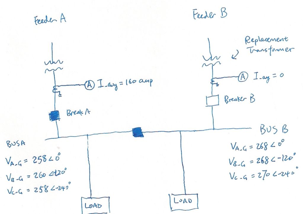
If you didn't have any load, you could push current from the higher set secondary to the lower set secondary. Is this the circulating current of concern?
But you do have load. And you have set the unloaded transformer terminal voltage close to, but above the terminal voltage of the loaded transformer. Is the concern that one xfm will be back-fed and the other, loaded xfm will trip? As Phill said, you will need the xfms base, impedance, turns ratio (at the tap setting chosen). Some of that may be hard to get.
ABB, Electrical Transmission and Distribution Reference Book has two pages explaining the parallel xfm model. It looks about like the attached.
View attachment 6958
A suggestion if the management wants to see a calculation. Use a similar model to the one attached. Caluclate the on-line xfm open circuit voltage. And you know the off-line xfm open circuit voltage. You should be able to then come up with a number for how the xfms will share the connected load.
After the manage nods their collectice corporate head, parallel them. When paralleled, there may be a slight rise in the terminal voltage as the on-coming xfm picks up part of the load Close the Secondary main, take time to measure the before and after currents, open the tie.
just thinking - not telling
ice