McGraw Edison Data Reader PC Cable Pinout

Status
Not open for further replies.

elegier

Member
Location
Reno, NV, USA
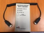
I have a problem I am hoping someone can help me with. I have some data on a McGraw Edison Data Reader (see photo attached). I have the cable for connecting the Data Reader to a Form 4C recloser or CL-4 and 5 regulator controls (spiral cable in the picture), but I do not have the cable to connect to a PC that allows downloading the data. It is a non-spiral gray cable with DB-9 connectors on each end (1 M and 1 F). I have tried a straight and null modem cables, to no avail. I have tried to find the pin-out for this PC cable on line, also to no avail. I have sent a request to @ Eaton (Cooper Power), but have not heard back yet. If anyone has one of these reader cables that I could borrow to get the pin-out or have one of your techs determine the pinout for me. Any help you could provide would be greatly appreciated. Thanks Ed
 

Attachments

  • Data Reader.jpg
    Data Reader.jpg
    31.4 KB · Views: 1
160919-2418 EDT

elegier:

The cable shown in your photo appears to possibly be a DB9 to DB9 of some sort. If this was not also for RS232 communication to a PC, then it should not even be mentioned. It is of no importance.

Does your logger have an AC power supply? If so plug it in, and turn on the logger. This should apply power to the RS232 output circuitry.

In a powered but rest state the RS232 transmit pin is at a negative voltage between about -5 and -15 V relative to the internal supply. Transmit is either pin 2 or 3 relative to pin 5 on a 9 pin connector, or pin 7 on a 25 pin connector. The RS232 common is typically connected to the equipment chassis. Thus, the RS232 common is likely connected to the 4-40 bushing that holds the connector to the chassis.

If hardware handshake is not required for communication, then you only need pins 2, 3, 5 or 7. You can use a Simpson or DVM to check the pin voltages. Determine whether your transmit pin is 2 or 3 on the logger. The logger transmit pin on the logger must be connected to the receive pin at the PC The PC receive pin is 2.

The PC transmit pin is 3 and this must be connected to the logger receive pin. The PC common pin, 5, must be connected to the logger common pin (5 on a DB9, and 7 on a DB25).

Other information is needed to determine whether hardware handshake is use. A scope can be useful if more detailed testing is required.

.
 
Eaton provided the Pin-out for the cable

Eaton provided the Pin-out for the cable

160919-2418 EDT

elegier:

The cable shown in your photo appears to possibly be a DB9 to DB9 of some sort. If this was not also for RS232 communication to a PC, then it should not even be mentioned. It is of no importance.

Does your logger have an AC power supply? If so plug it in, and turn on the logger. This should apply power to the RS232 output circuitry.

In a powered but rest state the RS232 transmit pin is at a negative voltage between about -5 and -15 V relative to the internal supply. Transmit is either pin 2 or 3 relative to pin 5 on a 9 pin connector, or pin 7 on a 25 pin connector. The RS232 common is typically connected to the equipment chassis. Thus, the RS232 common is likely connected to the 4-40 bushing that holds the connector to the chassis.

If hardware handshake is not required for communication, then you only need pins 2, 3, 5 or 7. You can use a Simpson or DVM to check the pin voltages. Determine whether your transmit pin is 2 or 3 on the logger. The logger transmit pin on the logger must be connected to the receive pin at the PC The PC receive pin is 2.

The PC transmit pin is 3 and this must be connected to the logger receive pin. The PC common pin, 5, must be connected to the logger common pin (5 on a DB9, and 7 on a DB25).

Other information is needed to determine whether hardware handshake is use. A scope can be useful if more detailed testing is required.

.

Eaton came through and was able to provide the pin-out (attached). Many thanks to all that replied. Ed
 

Attachments

  • Cable for Data Reader to PC.pdf
    59.9 KB · Views: 5
Sort of seems like someone wanted to be intentionally obscure, I can't see any reason for that wiring otherwise. The bog-standard DE-9 pin-out has been around for, what, 30 years? (And the DB-25 for a lot longer.)

On the PC side
2 receive (to PC)
3 transmit (from PC)
5 ground/reference
7 request to send from PC
8 clear to send to PC

I agree, they want you to buy their cable and not use one that is readily available. The problem arises when the equipment is still in service and the manufacturer no longer makes the special cable. Thanks Ed
 
Sort of seems like someone wanted to be intentionally obscure, I can't see any reason for that wiring otherwise. The bog-standard DE-9 pin-out has been around for, what, 30 years? (And the DB-25 for a lot longer.)

APC uses a bastardized pinout on their SmartUPS line. It's a holdover from when they used dumb signaling (contact closure rather than RS-232)

image002.gif
 
Status
Not open for further replies.
Top