Minisplit Nameplate Data

Status
Not open for further replies.

wwhitney

Senior Member
Location
Berkeley, CA
Occupation
Retired
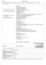
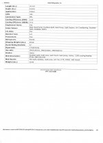
I've only looked at a couple minisplit outdoor unit nameplates, but the ones I have looked at list compressor RLA, fan FLA, and MCA. And it's not the case that MCA = 1.25 * RLA + FLA, MCA is larger than that.

Is this because the outdoor unit typically provides power for the indoor unit, so the MCA includes the load of the indoor unit? In which case for outdoor units that can connect to multiple indoor units, the MCA would have to include the worst case configuration in terms of number and size of indoor units. In that scenario, is there any path in the NEC for determining the actual load / MCA for the given installation, rather than using a worst case nameplate rating?

Thanks,
Wayne
 
My answer is yes. In many systems the outdoor units does provide power for the fan inside.

I thought the mca is 125% of the Fla. Why is the rla being used
 
My answer is yes. In many systems the outdoor units does provide power for the fan inside.

I thought the mca is 125% of the Fla. Why is the rla being used

The manufacturer has already determined the circuit parameters for you. Just use the label information, no other calculations are needed.
 
I thought the mca is 125% of the Fla. Why is the rla being used
My limited experience with HVAC outdoor units is that they have a compressor, whose rating is called RLA, and a fan, whose rating is called FLA. The compressor RLA is generally larger than the fan's FLA. And so then MCA = 1.25 * RLA + FLA, in the simplest case where there are no other loads.

Cheers, Wayne
 
The manufacturer has already determined the circuit parameters for you. Just use the label information, no other calculations are needed.
I understand that. But my last question relates to the case where the outdoor unit can be installed along with various possible combinations of indoor units. Which leads me to the supposition that the nameplate data would cover the worst case combination of indoor units. (Is that correct?) In which case, when using some other combination of indoor units, if a load calc or circuit sizing were just a little too large for some reason, is there a mechanism within the NEC that would allow one to recalculate for the actual equipment installed?

Cheers, Wayne

The first step in determining the size of a Ductless System is to perform an engineering Heat Load of the structure, no "Rule of Thumb" by square foot.
Then you look up the engineering data from the manufacturer to match your Heat Load results. I only install Daikin.
The outside condensing unit can be selected for one or four inside units. The outside unit has a DC power supply for both inside and outside units. For larger systems requirements I usually install two or more outside units.
 

Attachments

  • Daikin - Multi Split Systems.pdf
    1.4 MB · Views: 9
Last edited:
The first step . . .
Yes, I understand all that. My question is about how the manufacturer determines MCA, and what flexibility the installing electrician has to do a sharper (more accurate) computation based on the actually installed equipment, when the nameplate covers the worst case of a range of possible installations.

On some single speed outdoor condensers whose nameplate I've looked at, it will list MCA, RLA for the compressor, and FLA for the fan. And in the simplest case, MCA = 1.25 * RLA + FLA. Sometimes MCA is a little more, which I attribute to some miscellaneous electronic or other load not broken out on the nameplate. And of course if that circuit also powers backup heat strips, the heat strips would be included in the MCA.

On the few mini-split outdoor units I've looked at, which support multiple heads, MCA > 1.25 * RLA + FLA by a fair amount. On the data for the unit you posted, that 4-port unit can support at a minimum indoor heads of 7+7+7 (kBTUs/hr, I assume) and at a maximum 12 + 12 + 15 or 9 + 9 + 9 + 12 (not sure which would use more power).

So if I looked up the power requirements of the indoor heads at the max configuration, and I call that ILA (for Indoor Load Amps), would I find that the name plate MCA = 1.25 * RLA + FLA + ILA? And if so, if I instead installed the minimum configuration of 7+7+7 on the indoor units, and I found that the ILA for those is lower, is there an NEC route for overriding the nameplate and calculating a new lower MCA? If not for the branch circuit, possibly still for an Article 220 load calc?

I guess the corollary for the last question is that if you have an outdoor unit whose rating exceeds the rating of the indoor heads, it's possible that the configuration is incapable for moving as much heat as the outdoor unit is rated for. And the nameplate RLA would be based on that rating. If I could get the power rating information from the manufacturer for that specific indoor/outdoor configuration, could I use that updated (lower) RLA in computing a new MCA, or for an Article 220 load calc?

Probably the answer is that you're just stuck with the nameplate data regardless, but I thought the questions worth asking. I guess another possibility is that a manufacturer might be willing to send you a new nameplate with updated figures for your exact configuration; have you ever heard of that?

Cheers, Wayne
 
The NEC 2017 440.4 requires that you use the nameplate information. Attached is more information from Daikin. Daikin - Multi Split Heat Pump Systems Data  _Page_1.jpgDaikin - Multi Split Heat Pump Systems Data  _Page_2.jpgDaikin - Multi Split Heat Pump Systems Data  _Page_1.jpg
 

Attachments

  • Daikin - Multi Split Heat Pump Systems Data  _Page_3.jpg
    Daikin - Multi Split Heat Pump Systems Data _Page_3.jpg
    1,015.7 KB · Views: 6
  • Daikin - Multi Split Heat Pump Systems Data  _Page_4.jpg
    Daikin - Multi Split Heat Pump Systems Data _Page_4.jpg
    836.6 KB · Views: 7
I see nothing in those sheets about FLA, LRC, MCA, MOCP. What are you trying to show with these?

The original poster wanted additional information for other purposes, maybe I should have Emailed it to him instead, rather than posting it on line. I apologize.
The bottom line is that you should only go by the label on the equipment, per NEC 2017 440.4
 
The ductless systems are the way to go ... They are constantly evaluating the load 24/7. I believe this is the best way to HVAC your structure. Duct systems are a waste of money and energy.
 
I don't know if this is all of them but the mini splits I've installed for 2 or 3 zones were specific and had extra lines and terminals for those other zones on the outside unit. The name plate for a 2 zone mini split was correct for its application.
 
The ductless systems are the way to go ... They are constantly evaluating the load 24/7. I believe this is the best way to HVAC your structure. Duct systems are a waste of money and energy.

A tangent to the original thread (the horrors!), but ducting has its place.

In particular the smallest available minisplit heads are too large for small rooms. In this case you want to share the load between several rooms, and ducting is a good way to achieve this.

Back to the OP, I spent some time locating the published schematics for the minisplit units in my house. Would these help your understanding of the way these unit's nameplates are calculated?

Jon
 
Status
Not open for further replies.
Top