Motor cap sizing help...?

Status
Not open for further replies.

brantmacga

Señor Member
Location
Georgia
Occupation
Former Child
Trying to get this dryer fan going on a grain bin at the farm. The capacitors were shot. The markings were gone.

I guessed at the start capacitor size using the 30-50 rule and struck out I think.

The motor SOUNDS fine but it’s pulling 215A to start, and trips the breaker after a few seconds.

It’s a 10-12HP 215TZ frame motor.

Any help on sizing the capacitors?

Pic of nameplate ....

6a997c26b8fd712a628326e0268f0971.jpg


Sent from my iPhone using Tapatalk
 

ActionDave

Chief Moderator
Staff member
Location
Durango, CO, 10 h 20 min from the winged horses.
Occupation
Licensed Electrician
Trying to get this dryer fan going on a grain bin at the farm. The capacitors were shot. The markings were gone.

I guessed at the start capacitor size using the 30-50 rule and struck out I think.

The motor SOUNDS fine but it’s pulling 215A to start, and trips the breaker after a few seconds.
Might be a stuck starting switch. You'll need to knock off the rear end bell to inspect it, but you can put your amp meter around the lead going to the starting cap, amps should drop in less than one second.

Any help on sizing the capacitors?
That's a Grainger brand motor. You can call them.
 

Jraef

Moderator, OTD
Staff member
Location
San Francisco Bay Area, CA, USA
Occupation
Electrical Engineer
It's not simple, but you can make an educated guess using the tools on this page...
but I too recommend checking out the centrifugal switch first. That may be why the old one failed so if it's still stuck, your new one will fail too.
 

Murphy79

Member
Location
Kansas City , MO
Occupation
Master Electrician/ Elelectrical Contractor/Instructor/ Solar
Article 460 & T430.248

Article 460 & T430.248

I would start by sizing capacitor @ 135%...hope this helps.:cool:

your motor's FLC appears to be 50a for your motor even though the nameplate is provided....sometimes you have to use the FLC in certain situations.


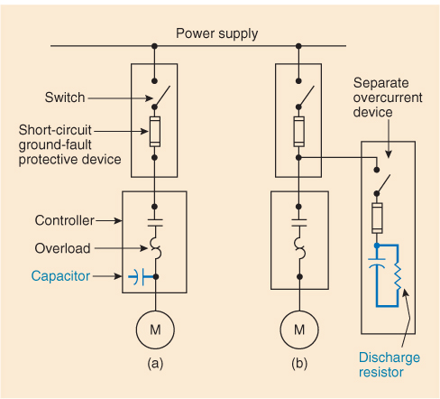
Where a capacitor is connected on the load side of the motor overload relays [see Exhibit 460.1, diagram (a)], the line current will be reduced due to an improved power factor, which must be taken into account when selecting the rating of a motor overload device. A value lower than that specified in 430.32 should be used for proper protection of the motor.
The most effective power factor correction is obtained where the individual capacitors are connected closest to the inductive load. Capacitor manufacturers publish tables in which the required capacitor value is obtained by referring to the speed and the horsepower of the motor. These values improve the motor power factor to approximately 95 percent. To improve a plant power factor, capacitor manufacturers also publish tables to assist in calculating the total kVAr rating of capacitors required to improve the power factor to any desired value.


Unless the exception applies, the overcurrent device must be separate from the overcurrent device protecting any other equipment or conductor. See Exhibit 460.1, diagrams (a) and (b).

EXHIBIT 460.1 Methods of connecting capacitors in induction motor circuit for power factor correction.
image_05cce57b-293c-11e7-97ae-8b53bde9d5f6.jpeg


460.8(C) Disconnecting Means.

A disconnecting means shall be provided in each ungrounded conductor for each capacitor bank and shall meet the following requirements:
  • (1)
    The disconnecting means shall open all ungrounded conductors simultaneously.
  • (2)
    The disconnecting means shall be permitted to disconnect the capacitor from the line as a regular operating procedure.
  • (3)
    The rating of the disconnecting means shall not be less than 135 percent of the rated current of the capacitor.
Exception: A separate disconnecting means shall not be required where a capacitor is connected on the load side of a motor controller.


460.9 Rating or Setting of Motor Overload Device.
Where a motor installation includes a capacitor connected on the load side of the motor overload device, the rating or setting of the motor overload device shall be based on the improved power factor of the motor circuit.
The effect of the capacitor shall be disregarded in determining the motor circuit conductor rating in accordance with 430.22.
 
Location
NE (9.06 miles @5.9 Degrees from Winged Horses)
Occupation
EC - retired
I would start by sizing capacitor @ 135%...hope this helps.:cool:

your motor's FLC appears to be 50a for your motor even though the nameplate is provided....sometimes you have to use the FLC in certain situations.


Where a capacitor is connected on the load side of the motor overload relays [see Exhibit 460.1, diagram (a)], the line current will be reduced due to an improved power factor, which must be taken into account when selecting the rating of a motor overload device. A value lower than that specified in 430.32 should be used for proper protection of the motor.
The most effective power factor correction is obtained where the individual capacitors are connected closest to the inductive load. Capacitor manufacturers publish tables in which the required capacitor value is obtained by referring to the speed and the horsepower of the motor. These values improve the motor power factor to approximately 95 percent. To improve a plant power factor, capacitor manufacturers also publish tables to assist in calculating the total kVAr rating of capacitors required to improve the power factor to any desired value.


Unless the exception applies, the overcurrent device must be separate from the overcurrent device protecting any other equipment or conductor. See Exhibit 460.1, diagrams (a) and (b).

EXHIBIT 460.1 Methods of connecting capacitors in induction motor circuit for power factor correction.
image_05cce57b-293c-11e7-97ae-8b53bde9d5f6.jpeg


460.8(C) Disconnecting Means.

A disconnecting means shall be provided in each ungrounded conductor for each capacitor bank and shall meet the following requirements:
  • (1)
    The disconnecting means shall open all ungrounded conductors simultaneously.
  • (2)
    The disconnecting means shall be permitted to disconnect the capacitor from the line as a regular operating procedure.
  • (3)
    The rating of the disconnecting means shall not be less than 135 percent of the rated current of the capacitor.
Exception: A separate disconnecting means shall not be required where a capacitor is connected on the load side of a motor controller.


460.9 Rating or Setting of Motor Overload Device.
Where a motor installation includes a capacitor connected on the load side of the motor overload device, the rating or setting of the motor overload device shall be based on the improved power factor of the motor circuit.
The effect of the capacitor shall be disregarded in determining the motor circuit conductor rating in accordance with 430.22.

Good information, but the OP is talking about the Start capacitor(s) in the motor, not Power Factor Correction.
 

Murphy79

Member
Location
Kansas City , MO
Occupation
Master Electrician/ Elelectrical Contractor/Instructor/ Solar
Thats why I posted Diagram

Thats why I posted Diagram

If you view diagram and the very far right ...the is a capacitor at the start circuit......He said the breaker keeps tripping when brings me to another issue...Is it really sized correctly......If I'm not mistaken the capacitor is used to momentary unbalance phases to induce rotation. The motor starts but shuts off...Is there a capacitor in the run windings?.....
 
Location
NE (9.06 miles @5.9 Degrees from Winged Horses)
Occupation
EC - retired
If you view diagram and the very far right ...the is a capacitor at the start circuit......He said the breaker keeps tripping when brings me to another issue...Is it really sized correctly......If I'm not mistaken the capacitor is used to momentary unbalance phases to induce rotation. The motor starts but shuts off...Is there a capacitor in the run windings?.....

In series with.
 

ActionDave

Chief Moderator
Staff member
Location
Durango, CO, 10 h 20 min from the winged horses.
Occupation
Licensed Electrician
If you view diagram and the very far right ...the is a capacitor at the start circuit......He said the breaker keeps tripping when brings me to another issue...Is it really sized correctly.....
The diagram you posted has nothing to do with the OP and none of it is helpful
If I'm not mistaken the capacitor is used to momentary unbalance phases to induce rotation. The motor starts but shuts off...Is there a capacitor in the run windings?.....
Since it's clear you know very little about cap start motors how bout you just read and not type.
 

GoldDigger

Moderator
Staff member
Location
Placerville, CA, USA
Occupation
Retired PV System Designer
If you view diagram and the very far right ...the is a capacitor at the start circuit......He said the breaker keeps tripping when brings me to another issue...Is it really sized correctly......If I'm not mistaken the capacitor is used to momentary unbalance phases to induce rotation. The motor starts but shuts off...Is there a capacitor in the run windings?.....

There is a capacitor in series with the start winding. The diagram does not show a start winding, possibly because it is a one-line for a three phase motor.
The capacitor(s) in the diagram are switched and overload protected, but are in parallel with the entire motor (run winding and maybe centrifugal switch controlled start winding, all inside the single motor symbol. Therefore that capacitor is for power factor correction only.
 

brantmacga

Señor Member
Location
Georgia
Occupation
Former Child
I appreciate all the responses.... motors are far from my strong suit. After reading all these, I pulled it off and took it to an electric motor shop nearby. Going to let them go through it and figure it out.


Sent from my iPhone using Tapatalk
 

Cow

Senior Member
Location
Eastern Oregon
Occupation
Electrician
I did the same with a 10HP single phase 3 weeks ago also, dropped it off at a motor shop.

The motor shop knows what they are doing and they can check the windings out while they are at it. In our instance, we had caps blown, they replaced the caps and bearings and said the windings look great. I like knowing I'm reinstalling something that's been gone through and is going to last a long time after I leave. Seems worth it to me.
 

brantmacga

Señor Member
Location
Georgia
Occupation
Former Child
Motor cap sizing help...?

Starting amps of 255 @ 230v plus a minimum starting voltage. IDR ever seeing either one of those on a label.


Follow-up on this .....

Motor was returned this morning; they said it had some issues they fixed along with replacing the motor starter and heaters. I was told the capacitors I installed are the right size.

So this motor has a legit starting current of 255A. I had a 60A cb on this circuit and it won’t hold. I connected directly to the line side of the incoming feeder unfused, and after 6 seconds of 255A, it dropped to 40A.

The nameplate on the blower calls for a 45A circuit. Never seen this in my life.

I just ordered some sub-feed lugs for the loadcenter to see if it will hold on the 200A MCB.


Sent from my iPhone using Tapatalk
 

SceneryDriver

Senior Member
Location
NJ
Occupation
Electrical and Automation Designer
Six seconds to come up to speed is a long time for starting across the line. Something is wrong and it may not be the motor.

A big centrifugal blower with large inertia might take that long to come up to speed. Sounds like a good application for a soft start, but could one be applied to a single phase motor successfully?

If this was working before, and now it isn't, you have to ask: what changed? Did someone change sheave sizes on the fan's belt drive in an attempt to move more air through the grain, for instance? Are bearings somewhere else in the system going bad? What's the inrush when the motor starts unloaded and mechanically disconnected from the fan; does it still take six seconds for the current to drop?


SceneryDriver
 
Status
Not open for further replies.
Top