Motor starter control circuit

Learn the NEC with Mike Holt now!
Status
Not open for further replies.

Jimineye

Member
Location
Texas
Occupation
Electrician
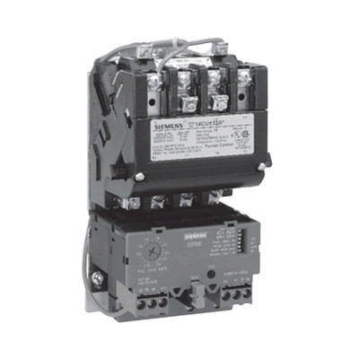
I have a Siemens 14DUt32A motor starter with an ESP200 overload attached to it. My question is regarding the wiring diagram that came with the starter/overload assembly. The wiring diagram shows a conductor coming off a grounded X2 in the control transformer, and terminating at 96, which is one side of a normally closed contact in the ESP200. There’s another conductor terminated at 96, labeled “A”, and the other end of this conductor appears to land on L2. This seems like it would cause a direct phase to ground short, so what am I missing or not seeing? I wish I could attach a screenshot of the wiring diagram, or find a ladder diagram of the same control circuit. I’m pretty handy at controls, but this one has me stumped 🤔. What even got me looking at it in the first place is this starter is part of an alternating starter control assembly for an air compressor - two motors, two starters, with an alternating relay to switch motors. One of the starters crapped out (30+ years old), so I replaced the starter, and the new one’s coil won’t close. I’ve verified that I have 120v at the coil when it’s being called for, the jumpers are correct, and the external safeties (temp sensor, pressure switch, etc) are all functioning correctly. Sorry for the long soliloquy, lol. Any advice is greatly appreciated. Thanks in advance!
 

Russs57

Senior Member
Location
Miami, Florida, USA
Occupation
Maintenance Engineer

Assuming the above is "close enough".....I think they are just showing different options. You could power 96 direct from L2, or through a fuse connected to L2, or through a control transformer. Assuming you are using a control transformer make sure to remove any factory wiring from line side to motor starter coil/overload relay.
 

EC Dan

Senior Member
Location
Florida
Occupation
E&C Manager
I use the same type of motor starter here, albeit without the control transformer. Those diagrams must be showing alternate wiring like Russs57 mentioned. In my case, the control circuit starts at L1, goes through a pressure switch, then through the overload relay contact 96/95 to the coil and then to L2. If you were using single phase voltage for the coil via a control transformer, you could source the 120 V on one side of the coil and terminate at X0 (grounded terminal) on the control transformer after the overload relay (and all the safety switches).

How are you measuring 120 V at the coil? Are you measuring 120 V across the coil?
 

augie47

Moderator
Staff member
Location
Tennessee
Occupation
State Electrical Inspector (Retired)
They certainly could have done a better job of showing they were depicting alternate connection methods.
(The original diagram doesn't happen to show colors or some means to show they are alternatives ? )
 

Jimineye

Member
Location
Texas
Occupation
Electrician
I use the same type of motor starter here, albeit without the control transformer. Those diagrams must be showing alternate wiring like Russs57 mentioned. In my case, the control circuit starts at L1, goes through a pressure switch, then through the overload relay contact 96/95 to the coil and then to L2. If you were using single phase voltage for the coil via a control transformer, you could source the 120 V on one side of the coil and terminate at X0 (grounded terminal) on the control transformer after the overload relay (and all the safety switches).

How are you measuring 120 V at the coil? Are you measuring 120 V across the coil?
I’m measuring the coil voltage across the coil and from the 120 from the control transformer on the coil to ground.
 

Jimineye

Member
Location
Texas
Occupation
Electrician
They certainly could have done a better job of showing they were depicting alternate connection methods.
(The original diagram doesn't happen to show colors or some means to show they are alternatives ? )
Agreed. I know enough not to wire it as it’s shown, but for someone who doesn’t know any better and wire it exactly as shown on the wiring diagram, they could find themselves in big trouble. I usually will see a dotted or dashed line to represent an alternative way to wire something.
 

Russs57

Senior Member
Location
Miami, Florida, USA
Occupation
Maintenance Engineer
I agree the way it is shown stinks. I also admit to "guessing" the intent of the wiring diagram.

FWIW I generally take the grounded side of the control transformer, wire it through the overload relay. Common of HOA goes to coil, hand side direct to control transformer hot, auto side is return from pressure switches/safeties/etc.

That way folks can go to hand and determine if it is a control or motor stater problem in a hurry. A couple of pilot lights lets you know if you have control power (which is derived from main power so it proves both) and if controls are calling for motor starter to be pulled in.
 

synchro

Senior Member
Location
Chicago, IL
Occupation
EE
Is there an additional letter after 14DUt32A to indicate the voltage rating of the coil? Letter F is 120V, and letter A is dual voltage 120/240. According to the spec sheet "Dual voltage coils are wired on high voltage unless specified on order."
 

reagal beagal

Member
Location
Dallas
Occupation
Senior Electrician
Is there an additional letter after 14DUt32A to indicate the voltage rating of the coil? Letter F is 120V, and letter A is dual voltage 120/240. According to the spec sheet "Dual voltage coils are wired on high voltage unless specified on order."
The letter is "A". And that was the first thing I looked for was to make sure my jumpers were set right. The jumpers came in the 220v configuration and I changed them to the 120v configuration. Sorry I forgot my old log-in information so I created a new one, but I have since found my old log-in info. That's why the question was asked under one username (Jimineye) but is now being discussed under a different username (reagal beagal). Thanks again to all who have added their 2 cents to this thread, I greatly appreciate any info.
 
Status
Not open for further replies.
Top