Moving beyond single core single winding.

Status
Not open for further replies.

jim dungar

Moderator
Staff member
Location
Wisconsin
Occupation
PE (Retired) - Power Systems
Okay, now that we all agree that a single core single winding has a single flux which results in a single voltage 'direction'.
Please, bear with me on the usage of the concept of direction. Cutting the single winding into multiple sections, 50% and 20% are common points, does not change the direction of the 'created' voltages. Based on ANSI standard conventions this direction is in phase with the current.

Again allow me a little leeway, it is not uncommon to call the high potential terminal an odd number (i.e. X1), the low potential is an even number (i.e. X2), and indicate the direction of the voltage as an arrow pointing from low towards high (i.e. X4->X3).

So if I take two transformer coils, wound in the same direction on a common core, there will be a single voltage direction even though there are two voltages. Standard convention is to call them X1-X2 and X3-X4.
If I connect them in series one way would be X1-X2X3-X4 and my two voltage would add, because the direction of the voltages are 'in phase', we often indicate this by connecting the tail of one arrow to the point of the other (i.e. --->--->).
However if I connect them in series like X1-X2X4-X3, the two voltages would subtract because the direction of the voltages are 180? out of phase, which is indicated by connecting the tail of one arrow to the tail of the other (i.e. <------>).


Again, lets get agreement on this 'process' before we move on.
 

jumper

Senior Member
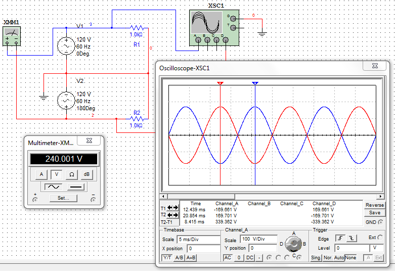
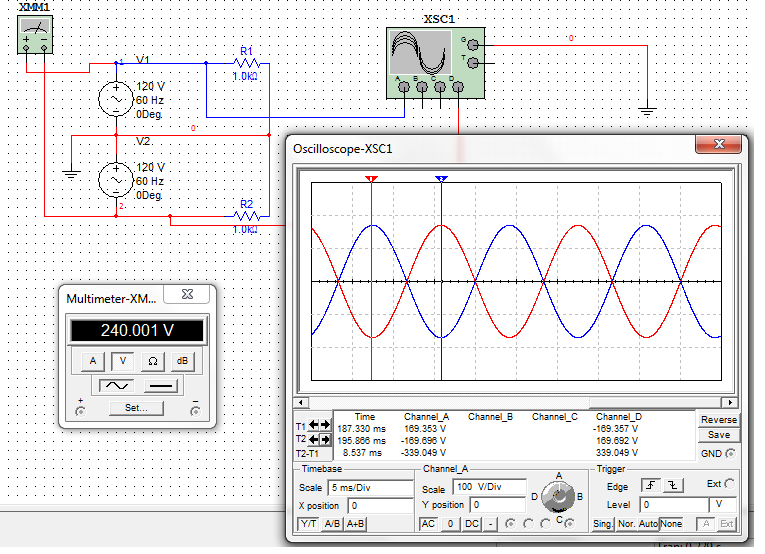
Jim, I made this two schematics, are they what you are referring to:


circuit1.png


circuit2a.png
 

jim dungar

Moderator
Staff member
Location
Wisconsin
Occupation
PE (Retired) - Power Systems
Yes, those represent the two conditions.
The output is the same, but where they came from is extremely different.

Without knowing how the sources are created, blindly making connections would definitely produce unexpected results.
 

gar

Senior Member
Location
Ann Arbor, Michigan
Occupation
EE
111101-1259 EDT

jumper:

Your two drawings together do not make sense. One is wrong, actually both.

In the upper drawing the little scope picture is wrong.

In the lower drawing the little scope is OK, the big scope is wrong, and the voltmeter is wrong.

In the big scope pictures the phase angle at the left is not an issue. That is simply how you choose to sync the scope.

I am also confused by what you are trying to say with your voltage source drawings inter-related with the labeled phase angle. Since the scope measurement is relative to common I would label the bottom voltage source of the upper drawing as 180 deg, and 0 in the lower drawing. The + and - and small sine waves in the voltage sources are OK.

.
 

jim dungar

Moderator
Staff member
Location
Wisconsin
Occupation
PE (Retired) - Power Systems
Since the scope measurement is relative to common I would label the bottom voltage source of the upper drawing as 180 deg, and 0 in the lower drawing. The + and - and small sine waves in the voltage sources are OK.

But the top sources are actually not out of phase at all, only the scope is.

So you want to 'name the angles' based on your measuring device and not the way the items are actually connected.

Remember the point of this exercise is to demonstrate how the 'arrows' relate to each other and the resultant addition or subtraction.
 

ggunn

PE (Electrical), NABCEP certified
Location
Austin, TX, USA
Occupation
Consulting Electrical Engineer - Photovoltaic Systems
I run into this all the time in audio. As long as you are talking about a single frequency, there is no difference between a situation with two identical AC waveforms where one is shifted 180 degrees out of phase from the other and one where they are in phase but polarity flipped, as long as you ignore stop and start points.

In audio, however, virtually all waveforms are much more complex, i.e., they are made up of many different frequencies. In the case of balanced audio connections, the popular vernacular says that one conductor carries a signal that is "180 degrees out of phase" with the signal on the other, which is clearly impossible, since the time delay necessary to shift any given frequency by 180 degrees is unique to that frequency. Polarity flipped is what they mean and it is not the same as a 180 degree phase shift in that scenario.
 
Last edited:

jumper

Senior Member
111101-1259 EDT

jumper:

Your two drawings together do not make sense. One is wrong, actually both.

In the upper drawing the little scope picture is wrong.

In the lower drawing the little scope is OK, the big scope is wrong, and the voltmeter is wrong.

In the big scope pictures the phase angle at the left is not an issue. That is simply how you choose to sync the scope.

I am also confused by what you are trying to say with your voltage source drawings inter-related with the labeled phase angle. Since the scope measurement is relative to common I would label the bottom voltage source of the upper drawing as 180 deg, and 0 in the lower drawing. The + and - and small sine waves in the voltage sources are OK.

.

Gar, where do you want me to put the o'scope leads?

I can switch the O and 180 easy enough.

I am just trying to put Jim's words to a circuit design to understand better what he is saying.
 

gar

Senior Member
Location
Ann Arbor, Michigan
Occupation
EE
111102-1800 EDT

jim:

I really don't know what preceded your first post in this thread.

Any measured voltage has to have two points to make a measurement. If those two points are identical, then the voltage difference is zero.

If I have two independent voltage sources with no connection between them, then I can not relate them to each other without some additional information.

If I connect two voltage sources to each other at a point, then I have to define a reference point for voltage measurements if I want to compare the voltages to each other.

Now consider the upper drawing. Use the common point between the two voltage sources as the reference point, and it also goes to the common terminal of the scope. Define the voltage of point 1 relative to common as v1 = V * sin t. For what I believe is the intent of this drawing the voltage of point 2 relative to common is v2 = V * sin (t + 180). So clearly v2 is a sinewave that is shifted 180 degrees from v1. This is what the big scope shows and that is correct. Also the voltmeter reading shown is correct assuming its averaging time constant is long compared to the frequency of the voltage sources.

Using the same analysis on the lower drawing and again assuming an intent, then v1 and v2 both equal V * sin t. Thus the waveforms would overlap and be identical on the big scope. The voltmeter would read zero because it is the difference of two identical voltages.

.
 

mivey

Senior Member
Please, bear with me on the usage of the concept of direction.
OK. I'll try to stay quiet about it until you move further.

Again allow me a little leeway...If I connect them in series one way would be X1-X2X3-X4 and my two voltage would add, because the direction of the voltages are 'in phase'...However if I connect them in series like X1-X2X4-X3, the two voltages would subtract because the direction of the voltages are 180? out of phase...

Again, lets get agreement on this 'process' before we move on.
Ok, I'm with you so far. I'm agreeing that V12 and V34 are in phase and will sum in the 1-2-3-4 or 4-3-2-1 direction to make a higher magnitude voltage across 1 & 4. I'm also agreeing that V12 and V43 are phase-opposed and will sum in the 1-2-4-3 or 3-4-2-1 direction to make a lower magnitude voltage across 1 & 3 .
 

jim dungar

Moderator
Staff member
Location
Wisconsin
Occupation
PE (Retired) - Power Systems
111102-1800 EDT
If I have two independent voltage sources with no connection between them, then I can not relate them to each other without some additional information.

If I connect two voltage sources to each other at a point, then I have to define a reference point for voltage measurements if I want to compare the voltages to each other.
The point is the sources are not independent, they are created from a single flux in a single transformer core.
A single transformer core has a single primary winding and a single secondary winding.
Would you agree that in order to solve a loop according KVL you need give a direction to that single secondary voltage as well as the secondary current?
Every 'transformer equivalent circuit' I have seen does just this, with the directions based on the primary connections.

Now take that single secondary winding and cut it into two pieces, nothing else changes. Following standard practice for modeling transformers this would yield two secondary voltage whose 'directions' are based on their relationship to the primary not to each other.
 

hurk27

Senior Member
The point is the sources are not independent, they are created from a single flux in a single transformer core.
A single transformer core has a single primary winding and a single secondary winding.
Would you agree that in order to solve a loop according KVL you need give a direction to that single secondary voltage as well as the secondary current?

Every 'transformer equivalent circuit' I have seen does just this, with the directions based on the primary connections.

Now take that single secondary winding and cut it into two pieces, nothing else changes. Following standard practice for modeling transformers this would yield two secondary voltage whose 'directions' are based on their relationship to the primary not to each other.

But because a transformer can have a secondary with a reversed wound coil (180? out) polarity of the secondary must still be established right, I know the normal convention is H1-H2 and X1-X2 which would always put the dot at the H1 and X1 but what if you came across a transformer that was no longer marked (I have had a few) where they used simple cheep wire marking tape that came off, now you are left with determining the polarity, of course there are tricks to find this and can be as simple as using a 9 volt battery, but that is another thread.

I bring this up as when using transformers in a buck boost configuration polarity is very important, and yes I have used the 9 volt battery trick a few times to figure out the polarity when the leads were not marked.
 

jim dungar

Moderator
Staff member
Location
Wisconsin
Occupation
PE (Retired) - Power Systems
Thank you for accepting my simplification. I am trying to get to how we can use an 'arrow' to represent a voltage direction. And that they can be combined using either additive or subtractive methods.

Ok, I'm with you so far. I'm agreeing that V12 and V34 are in phase and will sum in the 1-2-3-4 or 4-3-2-1 direction to make a higher magnitude voltage across 1 & 4.
Doesn't this case represent what is found in the actual construction of a center tapped transformer?

I'm also agreeing that V12 and V43 are phase-opposed and will sum in the 1-2-4-3 or 3-4-2-1 direction to make a lower magnitude voltage across 1 & 3 .
Doesn't this case represent what you have been saying about being able to connect two independent phase-opposed sources, like your generator example?
 

gar

Senior Member
Location
Ann Arbor, Michigan
Occupation
EE
111102-2005 EDT

jumper:

The scope leads positions are OK, and you have very professional nice drawings.

Replace the top big scope picture with the one that is on the lower big scope. Then modify the lower big scope picture by inverting the red curve. Maybe minutely change the magnitude of the red curve so both colors can be seen essentially on top of each other.

Change the bottom picture voltmeter to read 0 V.

In the top picture just above "1" put v1N = V * sin t. Make 1N a subscript. v1N means the voltage measured from point 1 to the ground wire. Below "2" put v2N = V * sin (t+180) or v2N = - V * sin t. This is a trig identity.

In the bottom picture I would still put the 1 and 2 in the same topological locations as on the upper picture, and eliminate 2 and 3 in the bottom picture.

In the bottom picture just above "1" put v1N = V * sin t. Make 1N a subscript. Below "2" put v2N = V * sin t.

Next go in and add the X1 thru X4 labels as appropriate adjacent to the voltage sources.

Doing these things I believe will accurately display what I think is the intent.

With correct big scope pictures I am willing to ignore the little scope pictures.

.
 

gar

Senior Member
Location
Ann Arbor, Michigan
Occupation
EE
111102-2041 EDT

jim:

When you split the secondary in the middle and do not connect the two secondaries together you can not define the voltage relationship of one to the other or make voltage measurements of one relative to the other.

Separately you can measure the voltage magnitudes and frequency, but you can not measure phase relationship without a common connection between them. You can not add or subtract the voltages without a connection, except in an abstract fashion.

You could add a third coil to sense the common flux to the two secondaries, and use that for scope sync, but that is really establishing a connection between the two secondaries.
 

jim dungar

Moderator
Staff member
Location
Wisconsin
Occupation
PE (Retired) - Power Systems
But because a transformer can have a secondary with a reversed wound coil (180? out) polarity of the secondary must still be established right, I know the normal convention is H1-H2 and X1-X2 which would always put the dot at the H1 and X1 but what if you came across a transformer that was no longer marked (I have had a few) where they used simple cheep wire marking tape that came off, now you are left with determining the polarity, of course there are tricks to find this and can be as simple as using a 9 volt battery, but that is another thread.

I have been trying to focus on the secondary of a single winding transformer as my starting point.
But you agree, it is possible and necessary to assign 'direction' or 'polarity' to transformer output based on its relationship to the primary winding.
 

jim dungar

Moderator
Staff member
Location
Wisconsin
Occupation
PE (Retired) - Power Systems
You could add a third coil to sense the common flux to the two secondaries, and use that for scope sync, but that is really establishing a connection between the two secondaries.
The third coil is the single primary winding, magnetic flux is the connection.
I started with a very specific set of conditions: a single primary winding, single core, single secondary winding. I then moved to splitting the single secondary winding into two pieces with identical relationships to the primary winding.
 

jumper

Senior Member
111102-2005 EDT

jumper:

The scope leads positions are OK, and you have very professional nice drawings.

Replace the top big scope picture with the one that is on the lower big scope. Then modify the lower big scope picture by inverting the red curve. Maybe minutely change the magnitude of the red curve so both colors can be seen essentially on top of each other.

Change the bottom picture voltmeter to read 0 V.

In the top picture just above "1" put v1N = V * sin t. Make 1N a subscript. v1N means the voltage measured from point 1 to the ground wire. Below "2" put v2N = V * sin (t+180) or v2N = - V * sin t. This is a trig identity.

In the bottom picture I would still put the 1 and 2 in the same topological locations as on the upper picture, and eliminate 2 and 3 in the bottom picture.

In the bottom picture just above "1" put v1N = V * sin t. Make 1N a subscript. Below "2" put v2N = V * sin t.

Next go in and add the X1 thru X4 labels as appropriate adjacent to the voltage sources.

Doing these things I believe will accurately display what I think is the intent.

With correct big scope pictures I am willing to ignore the little scope pictures.

.

Okay, I can do that stuff. If is okay, I will rebuild them and PM them to you, or anyone else if they willing to look at them, before I post them. I do not want to clutter the thread with test models.

The small scope and meter (they are both green) are simulation icons in the software, they are not showing readings. Only the large scope and VOM pictures relay information.

The software is Multisims/Electronic Workbench if you are curious.
 

mivey

Senior Member
The point is the sources are not independent, they are created from a single flux in a single transformer core.
But the beauty of transferring the energy through a flux is that it provides isolation from the primary. We can use the voltages on the other side of the flux in a configuration that is different from the primary.

A single transformer core has a single primary winding and a single secondary winding.
Would you agree that in order to solve a loop according KVL you need give a direction to that single secondary voltage as well as the secondary current?

Every 'transformer equivalent circuit' I have seen does just this, with the directions based on the primary connections.
So here we are with direction. I thought that you were trying to go somewhere different but it appears you are still set on saying that both secondary voltages have to be taken in the same direction as the primary voltage.

Now take that single secondary winding and cut it into two pieces, nothing else changes. Following standard practice for modeling transformers this would yield two secondary voltage whose 'directions' are based on their relationship to the primary not to each other.
The "direction" of the primary only matters if we need a link back to the source, and then it only matters when we are making our connections, not every time we use the secondary voltages. We need the relative directions when banking multiple transformers to be sure we can get the voltages we need. We do not have to use the primary directions as the one direction across the entire secondary winding.

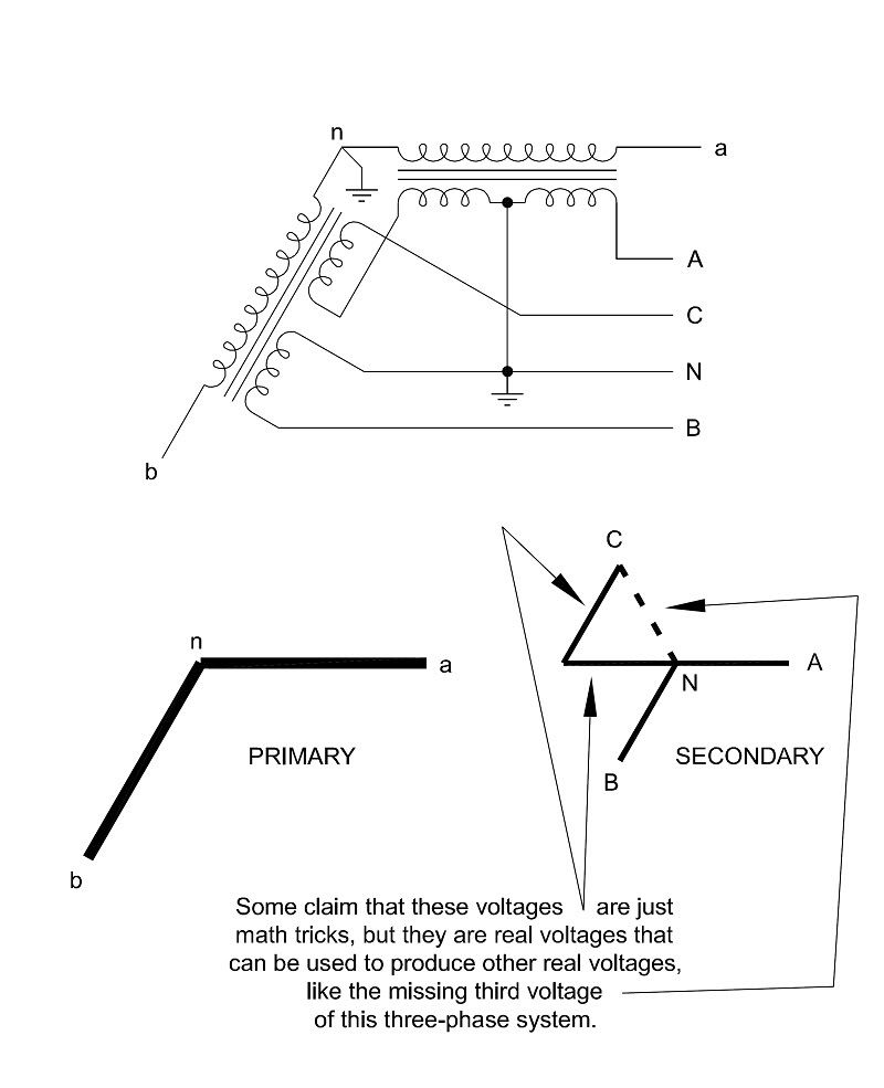
In moving beyond a single core winding, have you considered the "transformer equivalent circuit" for this transformer bank?:

Open-Wyeto4WWye.jpg
 

mivey

Senior Member
Thank you for accepting my simplification. I am trying to get to how we can use an 'arrow' to represent a voltage direction. And that they can be combined using either additive or subtractive methods.
I don't see a problem with that. I was trying to avoid a direction discussion until you got to your point but the first issue would be that we would normally not take the secondary of a single-phase transformer and connect it X1-X2X4-X3 because that is using the forces in opposition (reverse).

Doesn't this case represent what is found in the actual construction of a center tapped transformer?
The construction is described correctly as well as the connection we normally use.

Doesn't this case represent what you have been saying about being able to connect two independent phase-opposed sources, like your generator example?
Not at all. In this example, to get the voltage between 1 & 3 you have summed V12 (call that 120@0?) with V43 (call that 120@180?) and get the result of zero. This would not be the normal use of the two halves of the winding but am I trying to bear with your directions as you presented.

A run-down of what my two-generator example represents:

Transformer Configuration:
I have two identical transformers with single-bushing terminals labeled X1 for one side of the winding and X0 for the side that is tied to the tank and connected to Earth.

The Generators:
My generators also have a single-bushing for one output connection and the other connection is tied to the frame and connected to Earth.

One generator has a voltage Vp@0? from bushing to frame/Earth. The other has its shaft rotated 180? relative to the first generator, and has the voltage Vp'@180? from bushing to frame/Earth (relative to the other generator output). I am using the " ' " symbolt so we can keep up with the two different sources, voltages, etc.

The Transformer Secondaries:
Even though the loads may be on separate properties, they are ultimately tied through the Earth. If we look at both transformer secondaries at the same time, one will have a bushing-to-Earth voltage of V10=Vs@0? and the other will have a bushing-to-Earth voltage of V'10=Vs'@180?.

At that moment in time, if we look across both secondaries, the force in the direction from X1'-X0' is in the same direction as the force from X0-X1 (i.e., V'10 is in phase with V01). That is because the negative part of the voltage wave for V'10 is in phase with the positive part of the voltage wave from V10 (and vice versa).

The Secondary Voltages:
Therefore, in my phase-displaced source example, we have two voltages with their positive directions (as indicated by their polarity marks) in opposite directions, with each reaching their positive peak at 180? displaced from the other (i.e., V10=V'10@180?)

The Combined Voltages and Forces:
This results in two voltages, using a common connection called Earth, with positive voltages having 180? displacements. These two phase-displaced voltages produce forces that align and result in a double voltage across both secondaries. In other words, these two phase-displaced voltages can still have voltage forces that are in phase in the same direction.

Why Is That Different?:
Because they are single-bushing transformers with their tanks tied to Earth, we can't reverse the connections like we do in your X1-X2X4-X3 example so the polarities are physically fixed.

Why Is It Significant?:
1) This shows that you can indeed have two voltages with their positive voltages taken in different directions and with a 180? difference.

2) It shows that you can have these not just as a result of some math, but because they are physically generated and physically connected that way.

3) You can also use these voltages, with their positive directions as defined by polarity, to supply a 3-wire circuit.

4) Even though the positive forces are taken in opposite directions, and are displaced by 180?, the outputs can still work together to produce voltages that are in phase.

How Does It Relate To A Single Core?:
1) You could physically take the separate cores and join them at the common point and join the winding wires.

2) The result of #1 would be a primary source using two voltages displaced by 180?.

3) You have a set of secondary voltages that have directions already defined to be positive in opposite directions but displaced by 180?

4) #1, #2, & #3 would essentially give you the same transformer you have with with single-phase, center-tap transformer.

5) All of the above means that the direction we take to be positive does not have to be the same as the source, nor does that direction we take as positive have to be the same for both halves of the winding, and that we can do this without violating physics.
 
Last edited:

jim dungar

Moderator
Staff member
Location
Wisconsin
Occupation
PE (Retired) - Power Systems
Mivey,

Someday I hope you will be able to keep the discussion to a simple single core transformer with a single secondary winding direction. Honestly I stop reading your postings as soon as you start talking about how to use two source voltages. Of course you are free to spin discussions off on tangents, just like I am free to stop participating in them

But it appears you agree, that the two 'halves' of an industry standard center-tapped transformer winding are not connected in an actual physical 180? opposed arrangement.
 
Status
Not open for further replies.
Top