Moving beyond single core single winding.

Status
Not open for further replies.

mivey

Senior Member
Mivey,

Someday I hope you will be able to keep the discussion to a simple single core transformer with a single secondary winding direction. Honestly I stop reading your postings as soon as you start talking about how to use two source voltages. Of course you are free to spin discussions off on tangents, just like I am free to stop participating in them
Why the hostility? I'm trying to play along but how about let's keep it civil? Remember, I can't read your mind and what you write doesn't sound the same to everyone that reads it as it does when you read it.

You talked about cutting a single winding into two pieces, not me. You asked if we could be in agreement on the points you made so far before we moved along and then asked if one of those representations was the same thing I was representing. If you did not want to know what I was trying to represent, then don't ask:
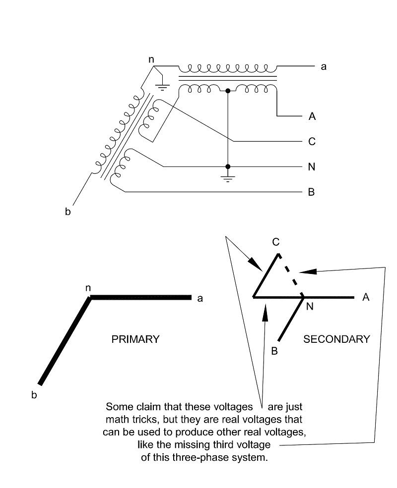
Doesn't this case represent what you have been saying about being able to connect two independent phase-opposed sources, like your generator example?

I'm still not sure where you are headed but I'll try to play along as I'm sure you have a point you are going to present soon.

So for the rest:
But it appears you agree, that the two 'halves' of an industry standard center-tapped transformer winding are not connected in an actual physical 180? opposed arrangement.
I agree that the voltages are not physically opposing each other. What I meant by the 180? statement is that the positive directions were opposite and that the positive peaks in those opposite directions happen at a 180? displacement.

Honestly, after all this time, the number of posts, the diagrams presented, and waveforms presented, that should be clear by now. My counter point is the presentation of an opposing concept because I think what works for a single transformer should work for many transformers as the physics do not change based on the application. You can always choose to not read posts, but that does little to promote communication and leads to misunderstandings about what someone is trying to say.


But carry on. I'll try to wait till you get to your point.
 

gar

Senior Member
Location
Ann Arbor, Michigan
Occupation
EE
111103-1135 EDT

jim:

How one views and relates different voltages in a circuit is dependent upon what are chosen as reference points.

Consider the center tapped secondary only, and label the outer ends A and B and the center tap N. Reference time to vAN.

First, use the center tap as the voltage reference point.
vAN = V * sin t, and
vBN = V * sin (t+180), or
vBN = - V * sin t .

Second, change the reference point to B.
vNB = V * sin t, and
vAB = 2 * V * sin t.

From trig identities (see Handbook of Mathematical Tables and Formulas by Burington)
sin (x+y) = sin x cos y + cos x sin y
let y = 180, then
sin (x+180) = sin x (-1) + cos x * 0 = - sin x


For ggunn:

A phase shift of a waveform does not have to result from a time delay. A three phase generator simultaneously produces at the same instant of time three voltages with phase shifts of 0, 120, and 240 degrees relative to some reference. For example use a point on the shaft for the reference.

On the other hand if I take two hoses, one 5 feet long and the other 10 ft long, and put one end of each hose at essentially the same point in front of an acoustic sine wave source, then put the other ends close to each other, and use instrumentation to monitor the output of each hose there will be a phase shift between the two outputs as well as a time delay of one relative to the other.

.
 

jim dungar

Moderator
Staff member
Location
Wisconsin
Occupation
PE (Retired) - Power Systems
I agree that the voltages are not physically opposing each other.

Honestly, after all this time, the number of posts, the diagrams presented, and waveforms presented, that should be clear by now.

At one time I thought we agreed which is why I started a new thread, but then I wasn't sure.

I wanted to find common ground on using 'arrows' to represent the connection of voltages as additive or subtractive, as this leads into the world of vectors and phasors. Which is are helpful to explain open-delta (arrows connected tail to point) and open-wye (arrows connected tail to tail). If we are caught up in a perceived physical 180? difference between A-N-C, how would we handle including the 90? difference of A-N-B in a high-leg connection?
 

mivey

Senior Member
At one time I thought we agreed which is why I started a new thread, but then I wasn't sure.

I wanted to find common ground on using 'arrows' to represent the connection of voltages as additive or subtractive, as this leads into the world of vectors and phasors. Which is are helpful to explain open-delta (arrows connected tail to point) and open-wye (arrows connected tail to tail). If we are caught up in a perceived physical 180? difference between A-N-C, how would we handle including the 90? difference of A-N-B in a high-leg connection?
Well then I say move forward to something new. The best I can recall, no one was saying the physical forces in the transformer are in opposition and, if they do, I'm on your side.
 

jim dungar

Moderator
Staff member
Location
Wisconsin
Occupation
PE (Retired) - Power Systems
How one views and relates different voltages in a circuit is dependent upon what are chosen as reference points.
That is not disputed (as far as I know).

However to ignore the physical construction and actual connection of transformer windings, simply to view things from an arbitrary point can lead to other problems.
In a previous thread I brought up the analysis of a simple 2-wire resistive load fed by a center-tapped winding versus that of a 3-wire load (once with one resistor connected L-N and the other connected L-L and the other time both connected L-N). Using the neutral as the 3-wire reference point results in either Van or Vbn being out of phase with its current. Yes, the math can be performed, but the results are not intuitive nor the same as the 2-wire circuit, which is not the case when using Van and Vnb.

Not all circuits or systems have a true neutral point, so why change methodology just because one exists. Analyzing a high-leg closed delta system based on the N point is more difficult than if a corner point was chosen.
 

mivey

Senior Member
That is not disputed (as far as I know).
Not disputed that I know of. The only dispute I recall was over whether or not the viewed voltages were real voltages.

However to ignore the physical construction and actual connection of transformer windings, simply to view things from an arbitrary point can lead to other problems.
Just like no one is saying there are physically opposed voltages in the transformer, I don't think any of use are ignoring the construction or connection either. We could not solve the circuit if we ignored those.

In a previous thread I brought up the analysis of a simple 2-wire resistive load fed by a center-tapped winding versus that of a 3-wire load (once with one resistor connected L-N and the other connected L-L and the other time both connected L-N).
In a simple circuit with a simple solution, I would also recommend using the voltages in phase in the same direction.

Using the neutral as the 3-wire reference point results in either Van or Vbn being out of phase with its current.
That was debated. The voltage and current of one half both had 0?. The voltage and current of the other half both had 180?. The neutral was dependant on the unbalanced load, as we would expect.

Yes, the math can be performed, but the results are not intuitive
I would say that depends on the circuit and the analysis, but I would agree for the simple circuit and analysis you had.

nor the same as the 2-wire circuit
Which I hope the importance will soon be forthcoming.

Not all circuits or systems have a true neutral point, so why change methodology just because one exists. Analyzing a high-leg closed delta system based on the N point is more difficult than if a corner point was chosen.
I'm sure we can cite pluses and minuses for either method. But on to vectors and phasors please.
 
T

T.M.Haja Sahib

Guest
In moving beyond a single core winding, have you considered the "transformer equivalent circuit" for this transformer bank?:

Open-Wyeto4WWye.jpg
Hi mivey,
Will you give more details on the principle of operation of this beautiful circuit?and where such transformer is used?(May be where full three phase supply unavailable)
 
Last edited:

Rick Christopherson

Senior Member
Not all circuits or systems have a true neutral point, so why change methodology just because one exists. Analyzing a high-leg closed delta system based on the N point is more difficult than if a corner point was chosen.
My question is, why use a common reference point in any case? It will complicate any analysis that is beyond just a simple set of 120V loads. In my opinion, if you use a common reference, then you should be using that common reference for all nodes, not just the power supply's nodes.

Don't get me wrong. I'm not saying it's wrong (no pun intended....I think).;) In my opinion, it just seems to complicate things. I'm sure it seems trivial on the face of it, but then consider what the analysis would be like if we were not assuming ideal conductors, but were instead calculating voltage drop and the loads? Now you would have voltage nodes that were isolated from the source nodes, and making calculations referenced back to a single reference node becomes a little more complex.

Yeah, I know. In the real world we would simplify things just so we don't have to do this, but I'm just sayin' :angel:
 

mivey

Senior Member
Hi mivey,
Will you give more details on the principle of operation of this beautiful circuit?and where such transformer is used?(May be where full three phase supply unavailable)
You are correct: it is used where only two phase conductors and a neutral are brought from a grounded wye distribution system.

The principle of operation is that the primary and secondary windings are isolated by a flux. Also, the secondary windings have a center point that can be opened, providing isolation between the two winding halves.

Each transformer has two secondary forces produced in phase with its primary force. With the isolation provided by the flux and the opening of the center tap, each secondary force can be independently used in the same direction as the primary or in a direction opposite from the primary.

See the illustration here:

SecondaryDirectionsandOpenWyeUse.jpg


So as you can see, a person is in coflict with physical realities if they claim that the only real voltages in the secondary of a center-tapped transformer are those that are taken in the same direction as the primary.
 
Last edited:

jghrist

Senior Member
Hi mivey,
Will you give more details on the principle of operation of this beautiful circuit?and where such transformer is used?(May be where full three phase supply unavailable)
This is an interesting connection. It isn't your typical open-wye open-delta connection which would be used to get 240 V delta from two 240 V transformer secondaries. You get 120/208 wye, with a single phase 240 V available (from A to the unmarked point opposite A).

For another exercise, figure out how to calculate the available fault current from the various secondary points (3? and ?-N), given the 1? transformer impedance Z. But maybe that's for another thread.
 

mivey

Senior Member
For another exercise, figure out how to calculate the available fault current from the various secondary points (3? and ?-N), given the 1? transformer impedance Z. But maybe that's for another thread.
You think? :D
 

mivey

Senior Member
...But on to vectors and phasors please.
...but before you do, you might do well to read my other post as it has some arrows in there for you.

I suspect when all is said and done, you might show us some arrows, phasor diagrams, maybe even some math, even a few theory quotes, give us a few more warnings about breaking laws and physics, and somehow try to make all these say that your choice to take both secondary voltages as positive in the same direction is the only choice that produces real voltages.

I will then present evidence to dispute your claims, and we will all come back to the fact that the positive direction choices we make when taking voltages from a source are exactly that: choices. Either direction is valid and neither choice makes one voltage real and the other just a math trick.
 
Status
Not open for further replies.
Top