Multiple Generators with Common Neutral

Status
Not open for further replies.

shortcircuit2

Senior Member
Location
South of Bawstin
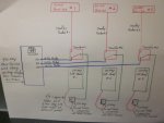
Take a look at the 1-line diagram below. The diagram shows a layout of 3 single phase 120/240volt separate generators feeding one building with simple 2-pole transfer switches.

Would there be trouble with the generator electronics and a common neutral between all 3 units?

Is there any concern if standard 2-pole transfer switches are used and 1 gen-set were to loose a neutral or hot leg?

Should the set-up use transfer switches that break the ungrounded conductor making them separately derived?
 

Attachments

  • IMG_6841.jpg
    IMG_6841.jpg
    134.3 KB · Views: 19
OK...no input here?

Others I have discussed this with find NO problem with multiple generators connected as shown in the diagram in post #1 without switching the grounded conductor thru the transfer switch as long as there is no potential between them.

shortcircuit
 
Hang on, to be clear each of the three feeders has a neutral with it right?

You are not running six hots and one neutral for it all right?
 
Electrically that would work
You mean no problem even when the common neutral the same size as the phase conductor?
Note:- The generators here are single phase and not three phase and so current from the three genrators add up arithmetically in the common neutral.
 
Hang on, to be clear each of the three feeders has a neutral with it right?

You are not running six hots and one neutral for it all right?

If he proposes one common neutral , it should be three times as large as the phase conductor. Isn't it?

Electrically that would work, code wise not so much.
I do not believe that is what he is proposing, but 215.4 permits up to three sets of feeders with a common neutral. I think sizing a common neutral conductor would depend on the calculated maximum unbalanced neutral current.
 
You mean no problem even when the common neutral the same size as the phase conductor?
Note:- The generators here are single phase and not three phase and so current from the three genrators add up arithmetically in the common neutral.
But the current doesn't necessarily add up arithmetically. It is unbalanced current which may come from either line. But otherwise yes, the calculated maximum unbalanced current could be as high as the total of all three ungrounded line currents.
 
Alright...some activity on this. I'll try to answer some of the comments.

This is only a 1-line diagram and does not show the neutral, but the neutral from each gen-set connects in common back thru the neutral bar in the main 400amp panel which also provides connection to the grounding electrode system because this is required as the gen-sets are NOT seperately derived with 2-pole transfer switches.

My original post seeked input on whether this would cause backfeed in anyway if one gen-set were to loose its own neutral or a hot leg...would it seek it from another???

This was explained to me that it would not happen because there is no potential from 1 gen-set to another.

One example given to me is if 3 homes were right next to each other with each having its own generator...this essentially would be the same thing. (considering they are fed from the same utility transformer)

Hope I explained this well enough for you.

shortcircuit
 
Yes.


I'm also curious...

WHY??? Everyone asks this 1st...why not just one 60KW generator?

Well...each gen-set feeds an area of the dwelling. Panel #1 feeds more important loads with panel #2 and #3 picking up not so important loads.

This gives flexablity to shut down gen-set #2 and #3 when the owner doesn't really need power to those areas of the dwelling...thereby saving an enormous amount of fuel.

Make sense so far?

shortcircuit
 
This is only a 1-line diagram and does not show the neutral, but the neutral from each gen-set connects in common back thru the neutral bar in the main 400amp panel

So it is not a common neutral, it is just a neutral. No more a common neutral than the neutrals supplying two different MWBCs.

My original post seeked input on whether this would cause backfeed in anyway if one gen-set were to loose its own neutral or a hot leg...would it seek it from another???

No not an issue but you put yourself on a slippery slope when you try to plan for a wiring defect.

What if the utility neutral opens supplying this building? Bad things could happen but that does not change how we would wire it.


One example given to me is if 3 homes were right next to each other with each having its own generator...this essentially would be the same thing. (considering they are fed from the same utility transformer)

Pretty much the same thing.
 
Next issue...the cord with the pin & sleeve assembly for each sub-panel.

WHY??? You ask.

Well the owner wants the flexablity to be able to disconnect one and connect it to another if a gen-set were to fail

Redundancy.

I don't think this part is OK.

Cord is not allowed in place of a permanent wiring method...right?

shortcircuit
 
So it is not a common neutral, it is just a neutral. No more a common neutral than the neutrals supplying two different MWBCs.

But Iwire...a neutral in a MWBC is from the same source...right?

So a hot in one MWBC would have potential to the neutral in another MWBC.

The 3 gen-sets are seperate sources so there would be no potential to the other thur a interconnected neutral.

A bit didfferent...right?
 
I don't think this part is OK.

Cord is not allowed in place of a permanent wiring method...right?
Correct, hence the question why.

Also, in order to use the #4 cord, you need OCP of 90-amps and a connected load at no more than 85-amps in order to comply with 110.14(C)1 unless you can document that the terminations of the cord are rated at 90c.
 
This is only a 1-line diagram and does not show the neutral, but the neutral from each gen-set connects in common back thru the neutral bar in the main 400amp panel which also provides connection to the grounding electrode system because this is required as the gen-sets are NOT seperately derived with 2-pole transfer switches.
Are you running the neutrals from the generators to the 400-amp panel and the hots to the transfer switches? If so, how are you doing this? Where do the neutrals and phase conductors separate?
 
Status
Not open for further replies.
Top