electriguy
Member
- Location
- United States
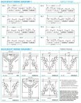
Welcome to the forum.I cant figure this diagram out. Figure DD is what I need to use, cant figure out the connections.
Should have added more info.. I need to just lower the voltage for a condensing unit from a high leg 120/240 to 120 208. Whats confusing me is b phase.. The line and load both connect to the same wires?
Yes, in an autotransformer connection, it is common to have one line serve as the 'reference leg', and as such it passes straight through the transformer.Should have added more info.. I need to just lower the voltage for a condensing unit from a high leg 120/240 to 120 208. Whats confusing me is b phase.. The line and load both connect to the same wires?
Please clarify which of the following the load requires:Should have added more info.. I need to just lower the voltage for a condensing unit from a high leg 120/240 to 120 208. Whats confusing me is b phase.. The line and load both connect to the same wires?
")
All most afraid to chime in, afraid some one will bite my head off again.
So if I am wrong please, I am apologizing now.
But the OP. said he wants to reduce the voltage not increase it.
I think that the DD is a boosting configuration.
Needs to use either CC or EE. configuration
Ronald
Polarity isn't marked so hard to tell which diagrams are buck and which are boost.All most afraid to chime in, afraid some one will bite my head off again.
So if I am wrong please, I am apologizing now.
But the OP. said he wants to reduce the voltage not increase it.
I think that the DD is a boosting configuration.
Needs to use either CC or EE. configuration
Ronald
We can guess by their arrangements... as Jim Dungar pointed out (though I think he got it backwards)... but it's not as certain as the manufacturer stating which configuration is which, or indicating polarity.Polarity isn't marked so hard to tell which diagrams are buck and which are boost.
We can guess by their arrangements... as Jim Dungar pointed out (though I think he got it backwards)... but it's not as certain as the manufacturer stating which configuration is which, or indicating polarity.
After a little investigation, that diagram appears to be from Acme. Here's a link to their documentation:Sorry, I didn't know different Transformers Numbered there Lines differently.
I was always taught that they where suppose to be a certain way.
This DD transformer should be a boost transformer. H1 through h4 + x1 through X4
should be additive.
H1 through H4 + X4 through X1 would be subtractive and would be a actual buck configuration.
Ronald
After a little investigation, that diagram appears to be from Acme. Here's a link to their documentation:
http://www.acmetransformer.com/~/media/inRiver/322941-13868.pdf
It also says diagram DD for bucking 240 to 208.
This DD transformer should be a boost transformer. H1 through h4 + x1 through X4
should be additive.
H1 through H4 + X4 through X1 would be subtractive and would be a actual buck configuration.
That's not an absolute....
If the source is connected to the LV terminals then the output has been boosted to the HV.
If the source is connected to the HV terminals then the output has been bucked to the LV.