JerielBrooks
Member
- Location
- NC
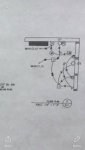
I understand the plugs switches and all. But there’s 2 circuits going to the time clock then the motor and then to what ever jm is? I have no legend. Thanks for you help understanding this part of it.
I understand the plugs switches and all. But there’s 2 circuits going to the time clock then the motor and then to what ever jm is? I have no legend. Thanks for you help understanding this part of it.
I understand the plugs switches and all. But there’s 2 circuits going to the time clock then the motor and then to what ever jm is? I have no legend. Thanks for you help understanding this part of it.
Hello could I please email you the drawing I’m talking about? You can’t see it well in the attachment I sent.I do not understand your question. Can you describe it better? JM?


That is all I have no legend. I have competition in company tmrw. I think I have the 3 and 4 ways down but I don’t understand wiring for the time clock,m, and jm whatever that is.
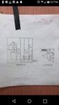
Also it shows a 12/2 feeding a plug then from there a 12/3 feeding another plug that shows as being split wired. Which I’m pretty sure is impossible unless I ran 2 12/3 Romex to the 1st plug. Thank you!!
Well, you could not run 12/3 from the first outlet to the second outlet when you ran 12/2 from the junction, so that has to be an error... unless they reversed the two and want an outlet run from the switches as well... like a work lamp on top outlet with the pins broke off for separate lives... but that would have to be at first outlet as feed from junction 2 is all NM cable...
Picture is pretty rough but I would put in NM12/2 from outlet 1 to outlet 2... as NM12/2 is run from Junction 2 to outlet 1...
not sure whatbJM is but as I said, figure a switch of some sort feeding through motor junction to the TC, or wired at motor but needing powered from TC... Would have to see the motor wiring specs to be sure, which you do not have. JM Could be a control panel of some sort controlling the motor... and so the power circuit from panel is to motor, TC is jumped from motor to TC and back, and JM is jumped from motor to JM and back..all wiring on motor...
or it could be like two way lights, where the power is switched from TC, and you have the control relay running from TC to JM and back to motor...
Sorry I cannot be more help...
thanks man