Need help wiring up a Honeywell (Generac) automated generator

Status
Not open for further replies.

crtemp

Senior Member
Location
Wa state
This is my first time wiring a automated generator and I have a question. Hopefully someone out there has experience wiring these and this will be a simple question.

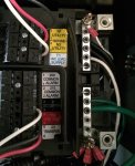
I purchased a Generac transfer switch that came with its own load center. Instead of getting the matching Generac generator my customer went to Costco and purchased a Honeywell generator. I was told that sometimes two different brands will have a difficult time communicating with each other but I was told the Honeywell generator is basically a Generac with a different name painted on it. When I looked at what generator models my transfer switch would work with, the Honeywell model number came up so I assumed I was good to go. Anyway long story short, The generator is not set in its permanent place but it was on site so I decided to rig it up and make sure everything was in working order before the sheetrock goes on (this is a single famliy dwelling by the way). When I originally wired the house I had not seen the generator yet so I pulled what I thought was correct. I pulled a 14-2 NM-B for the "sensing breaker" and a 14-3 NM-B for the transfer switch. When I went to hook it up I see there is another spot to land a wire that says it is for the battery charger. So now I figured that it needed a neutral wire so I tore out the 14-2 I ran for the sensing breaker and replaced it with a 14-3. I hooked it up and the generator readout claimed there was no power to the battery charger. Did I do something wrong?

Basically what should I be hooking up to the terminal B (white #3)?
 

Attachments

  • IMG_2356.JPG
    IMG_2356.JPG
    140.2 KB · Views: 2
  • IMG_2359.JPG
    IMG_2359.JPG
    75.5 KB · Views: 4

infinity

Moderator
Staff member
Location
New Jersey
Occupation
Journeyman Electrician
How is the other end of the 14/3 wired? The connections in photo #1 should be Black-DC common (-), Red-(+12) and White-(transfer).
 

GerryB

Senior Member
Generac has a pretty good tech support line. I think you are correct you need 6 wires. Do you have any indicator lights? I had a fuse (one of two) go bad on one I did that had something to do with the battery.
 

crtemp

Senior Member
Location
Wa state
How is the other end of the 14/3 wired? The connections in photo #1 should be Black-DC common (-), Red-(+12) and White-(transfer).


They were matched up at the transfer switch. Red was xfer, white was dc -, and black was dc+.
Both sides were the same.
The generator has a led display and when I would turn on power it would claim "no power to battery charger ".

There is no cell service up there so tech support is out.
 

Attachments

  • IMG_2360.JPG
    IMG_2360.JPG
    125.2 KB · Views: 1

crtemp

Senior Member
Location
Wa state
The label says 'see note below'. What does that note say?

The note doesn't make any sense to me.

Also I'm sure it doesn't matter what colors I use for dc+ dc- and xfer as long as they remain the same on both sides which they are
 

Attachments

  • IMG_2359.JPG
    IMG_2359.JPG
    118 KB · Views: 0

K8MHZ

Senior Member
Location
Michigan. It's a beautiful peninsula, I've looked
Occupation
Electrician
Is there 120 volts between T1 and either N1 or N2?

If so, can you locate the fuse for T1 and make sure it is there and not blown? Then check both sides of the fuse to N1, then N2 to make sure there is a 120 volt voltage diff. on both sides of the fuse holder.
 

infinity

Moderator
Staff member
Location
New Jersey
Occupation
Journeyman Electrician
The note doesn't make any sense to me.

Also I'm sure it doesn't matter what colors I use for dc+ dc- and xfer as long as they remain the same on both sides which they are

You're correct the conductor doesn't care what color it's insulation is however a standard DC circuit would use Black as the (-) and Red as the (+).
 

GerryB

Senior Member
Is there 120 volts between T1 and either N1 or N2?

If so, can you locate the fuse for T1 and make sure it is there and not blown? Then check both sides of the fuse to N1, then N2 to make sure there is a 120 volt voltage diff. on both sides of the fuse holder.


That was the problem I had. A blown fuse. I still have one left over, Bussman 5a time delay. Pretty sure that was the error code, battery not charging. The fuses are right there in the TS
 

kwired

Electron manager
Location
NE Nebraska
I recall hooking one up maybe about 7-8 months ago - terminals in the generator look pretty familiar but I had a a service main/transfer switch instead of a loadcenter type transfer switch. I remember needing to install an aux fuse block (that was supplied with the unit) in the transfer switch enclosure and it needed to connect to the "common" off one leg of the transfer switch and bring 120 volts for battery charger to that "terminal 3" in question at the genset. This would power the charger whether the switch was in normal or standby position.
 

iwire

Moderator
Staff member
Location
Massachusetts
You're correct the conductor doesn't care what color it's insulation is however a standard DC circuit would use Black as the (-) and Red as the (+).

Ok good to know. Are all colors except black positives?

Just to interject here, red and black are just design choices. I would not call them standard. A lot of industrial machinery uses other colors, fire alarm uses other colors etc.

And sometimes if either of the conductors is grounded the NEC requires the grounded one to be white.

With solar work either the positive or negative might be grounded dependent on the equipment used. So white could be positive or negative.
 

kwired

Electron manager
Location
NE Nebraska
Just to interject here, red and black are just design choices. I would not call them standard. A lot of industrial machinery uses other colors, fire alarm uses other colors etc.

And sometimes if either of the conductors is grounded the NEC requires the grounded one to be white.

With solar work either the positive or negative might be grounded dependent on the equipment used. So white could be positive or negative.
If it is less then 50 volts - 200.7 (B) doesn't require white, gray, or three continuous white stripes for grounded conductors unless 250.20(A) requires the system to be grounded - and 250.20(A) only applies to alternating current supplies.

Something I haven't noticed before is that 250.20(A) would require a 24V control circuit of a HVAC unit supplied by 480 volts (something pretty common) to have the 24V control system grounded - which they usually are. But this would also mean 200.7(B) would require the grounded conductor of that circuit to be white, grey, or have 3 continuous white stripes. I never see that done, and it goes against the color codes commonly used for HVAC controls and would have the HVAC guys all messed up. You don't change colors on many of those guys or they are on a different planet when it comes to figuring anything out.

Maybe listing and instructions is a way around that requirement??
 

iwire

Moderator
Staff member
Location
Massachusetts
If it is less then 50 volts - 200.7 (B) doesn't require white, gray, or three continuous white stripes for grounded conductors unless 250.20(A) requires the system to be grounded - and 250.20(A) only applies to alternating current supplies.

Which may well be why I said 'sometimes'. :thumbsup:


Something I haven't noticed before is that 250.20(A) would require a 24V control circuit of a HVAC unit supplied by 480 volts (something pretty common) to have the 24V control system grounded - which they usually are. But this would also mean 200.7(B) would require the grounded conductor of that circuit to be white, grey, or have 3 continuous white stripes. I never see that done, and it goes against the color codes commonly used for HVAC controls and would have the HVAC guys all messed up. You don't change colors on many of those guys or they are on a different planet when it comes to figuring anything out.

Maybe listing and instructions is a way around that requirement??

I think it just further illustrates how little a color really tells us.

As far as 'color codes commonly used for HVAC controls' even those seems to be falling out of favor. I see more and more HVAC equipment, even small split systems using data signals between thermostats and other equipment.
 
Status
Not open for further replies.
Top