I've put plenty of effort into the subject. I suggested you try a few examples on for size, and you've not, so I'm not putting a lot of truck into the comments you've made about my "teaching" skills.
You are just not following what I am saying. Look at my posts #136 and #144 and see if you can figure them out.
The bottom line, regardless of what you or I may or may not know, is that utilities have concerns about declining power factor caused by PV installations.
I'm well aware of the utilities' concerns as I am one of the utility people that addresses them and the associated costs. I design the system, design & verify the service, design & verify the meter setup, design & verify the utility rates, calculate the rates, verify the billing, analyze the financials, allocate the costs for the rates, develop software to help with all of these items, write policies and procedures for different utility areas including distributed generation and metering, as well as teach system design, rate design, billing, and cost allocation to utility personnel.
You might think the issue of generators not supplying vars is unique to PV systems but it is not.
And while you seem to feel that slapping a negative sign in front of power factor is a dumb idea, and perhaps even that anyone who'd suggest doing so is an idiot,
As I have said, there is no problem with using the sign as an indicator of other things and there are at least three ways that I have seen the sign in front of the pf used. The problem is with you trying to say that the power factor itself has a positive or negative nature.
Maybe that is where we have a misunderstanding.
The power factor is an indication of how the capacity is being utilized. It is strictly a percentage with no sign. To make the physical analogy, it is the percentage of the conductor carrying real current to the percentage of the conductor carrying real plus reactive current.
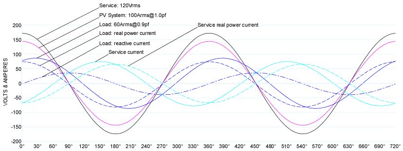
the facts are unavoidable -- completely and totally unavoidable -- that the grid operator will see two different ratios between VAs and VARs for a customer with 100KVA consumption at 90% PF and 100KVA production at 90% PF.
What the grid operator sees has nothing to do with the power factor value stored or any associated sign. What the grid operator sees is based on a kW and kvar measurement (and kVA but that is not important at this point). The power factor is a secondary piece of information and can be completely left out of the calculation with no impact. If the power factor number will not impact the calculations, neither will any sign you stick in front of it.
A study out of the University of Michigan, I believe it was (it came from Michigan -- not sure if UofMich did the work, but I know it was a Michigan thing) calculated costs for voltage and frequency regulation as PV penetration increased. As I recall, at 20% penetration, they put the regulation costs at about the same as the bulk (wholesale) generating costs. All this is from fuzzy memory, but that's beside the point -- there's going to be an impact and figuring out what it is and figuring out how to apportion the costs are going to be part of what goes on.
No doubt that if PV generators do not contribute vars, they will impact the grid costs. But this is the same scenario the power industry has faced with other generation on the grid. What made the PV inverter different from some is that they started out with no means to provide the vars. That is no longer the case with the new inverters.
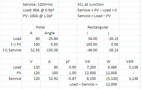
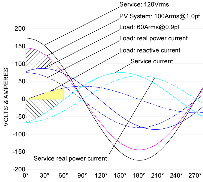
And while I suspect we're about fed up with each other, I'd encourage you to consider an example at the 20% point -- 1MVA at 90% PF with and without 200KVA at the same 90% PF being fed into the grid from a PV installation. Calculate the VARs that the utility needs to produce in both cases and the percentage of VARs to VAs from the utility perspective. Give that an honest go and you'll either see what I'm getting at or not.
I already understand what you are getting at: it makes a difference whether or not the PV inverter provides vars to the grid or not. That has nothing to do with saying power factor can be positive or negative. The sign is an indicator of something else.
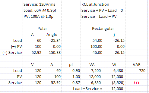
What you are not getting is that the calculations are not dependent on the number you use for power factor. That is not the way the utility meter works. Since you are concerned with what I see as a utility, let's look at the utility metering standards. The meter standards use quadrant metering and the power factor is a secondary calculation.
In the following sets, you could completely drop the power factor percentage with no difference in the result. I have shown the quadrant metering flag as well as the power factor that would come from the meter. I have added the signed pf notation used by Fluke PQ meters (what you are proposing) as well as two other notations I have found.
None of the signed pf values have any impact on the billing or cost as they are not used as part of the billing or cost calculation but are presented as secondary information. The reason they are not used is because there is no standard for that type notation and it can vary depending on who you are talking to. Four-quadrant metering is the IEEE standard for power metering and is what our utilities use.
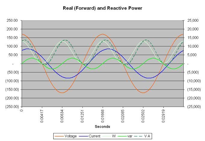
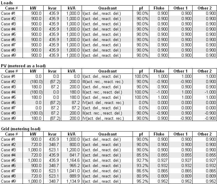
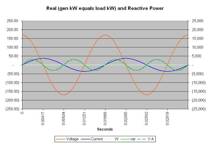
Here is PV output (and/or load) that is less than the grid load for different PV load/output scenarios:
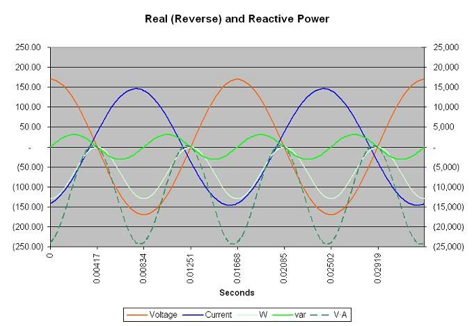
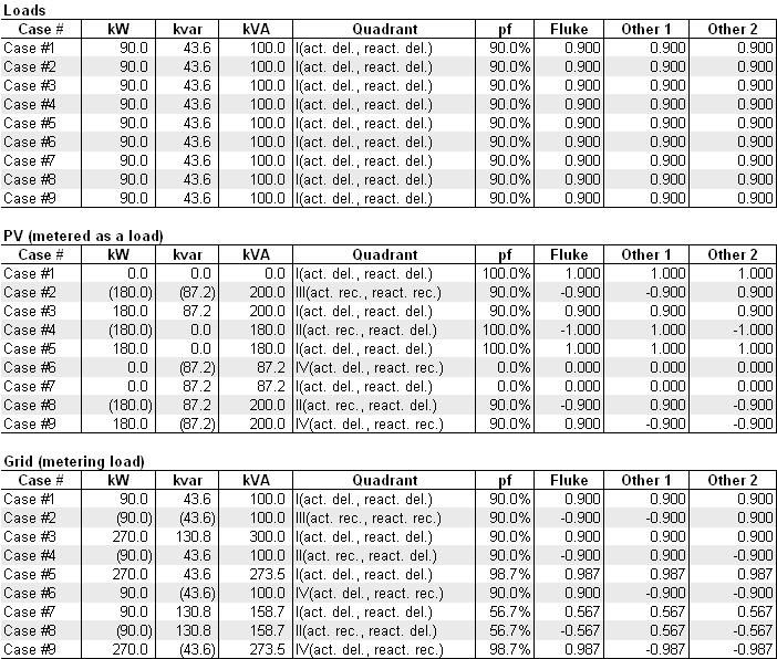
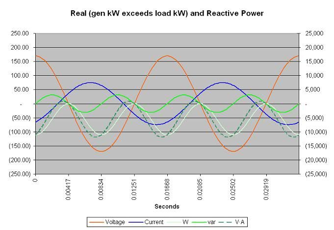
Here is PV output (and/or load) that is greater than the grid loads for different PV load/output scenarios:
Hopefully I have avoided any typos but either way, you should get the idea.

") ) ...anyone???
) ...anyone???