neutral current calculation....again

Status
Not open for further replies.

basicbill

Member
Location
Western Canada
Hi,
I read through all 150 or so postings on the unbalanced neutral thread and I examined the xls calculators but I have a lingering question that I hope you all can answer.

My scenario is this....120/208V, 3 phase 4 wire system. Three individual single phase motors, all at different pf's.

I plug the variables into the neutral calculator to get an answer.....no problem.

My question is this....why does the spreadsheet utilize the phase angles as leading the phase voltage? For instance if one of my motors has a pf of .707 on phase A, shouldn't the calculator use an angle of -45 degrees?

Thanks in advance!
BB
 
The neutral calculator spreadsheet is at ...

http://forums.mikeholt.com/showthread.php?t=93575&highlight=neutral+calculator&page=8

If you unlock it with 'abracadabra' you can see the formula used to calculate the phase angle.

Once again, it appears that the phase angles are considered to be leading and not lagging as would be appropriate.

Thanks again.

Ahhaa! That's the calculator I made. Good thing I edited the post, or else I wouldn't have remembered why ;)

Explanation: When working in the positive phase displacement angle domain, all phasor angles are reversed (i.e. multiplied by -1). The reason for this is because phase angle displacement is actually in the negative domain. We always assign 0? to Phase A... but Phase B lags Phase A by 120?, which is technically a phasor angle of -120?, and Phase C is -240?.

A lagging power factor has a negative phase angle displacement, which gets added to the voltage phase angle. For example, a lagging PF of .707 is -45?. If this load is connected to Phase A, the phase angle of the current would be 0? + (-45?) = -45?. When working in the positive domain for phase angle displacement it would be 0? + (-1 ? -45?) = 45? for the lagging PF.

I actually prefer working the actual (negative) domain for phase angles to avoid the confusion. Unfortunately, I seem to be in the minority... so I made the calculator work in a manner that others seemed to prefer :cool:
 
thanks Smart.
If I understand you correctly, you are saying that our phasor representations, where A phase is drawn at 0, B at 120 and C at 240 ..... with a ccw rotation actually should represent lagging currents as lagging ccw?

<light bulb slowly illuminating>
 
thanks Smart.
If I understand you correctly, you are saying that our phasor representations, where A phase is drawn at 0, B at 120 and C at 240 ..... with a ccw rotation actually should represent lagging currents as lagging ccw?

<light bulb slowly illuminating>

Yes.

In the positive phase angle domain, voltage phasors initially A@0?, B@120?, and C@240? would rotate CW. That is, each phasor would rotate about its tail point in the CW direction as time elapses. At t=1/3 cycle, voltage phasor A would be at -120?, voltage phasor B would be at 0?, and voltage phasor C at +120?. For a lagging current, the phase angle would be to the CCW side of the voltage angle.

If you prefer everything to be in the negative domain, the calculator shouldn't be to hard to change. If you need my help, just "holler"... :grin:
 
Wait a minute:

Wait a minute:

thanks Smart.
If I understand you correctly, you are saying that our phasor representations, where A phase is drawn at 0, B at 120 and C at 240 ..... with a ccw rotation actually should represent lagging currents as lagging ccw?

<light bulb slowly illuminating>

Smart must be left handed. I cannot see that phase sequence has anything to do with power factor.

An inductive impedance carries a positive phase angle. Dividing this impedance into the applied voltage yields a current which lags the voltage. For example, each of these cases yields a current lagging by 45 degrees.

V @ 0/Z @ 45 = I @ -45
V @ 120/Z @ 45 = I @ 75
V @ -120/Z @ 45 = I @ -165

The current angle is the difference in the voltage angle and impedance angle.

Also, PF is the same for + or - angles--always positive.

KISS = Keep It Simple Smart.

Your taking the easy way out...

Is 120? actually 120? or is it -240?...

...and is -120? actually 240? or is it -120?


I can look at your equations and by the result, I know your phasor rotation is CCW.

If you can teach everyone to use 0?, -120, and -240? for phases A, B, and C voltages, respectively, then I can keep it as simple as it gets... :grin:

Of course! It is silly to take the hard way. Furthermore, whether you label an angle as negative or use its positive equivalent makes no difference.

Now the rotation of rotating phasors is always CCW, and rotating phasors are functions of time which are useful as a way of illustrating the varying components of a sinusoid. But we are dealing with fixed phasors which are not functions of time and therefore cannot rotate.

But you are really talking of phase sequence. Is it ABC, or is it ACB? And this does not matter either. The phase angles of the load current (relative to the applied voltage) are unaffected.

There seems to be widespread confusion between fixed and rotating phasors, and at one time I had a reference which discussed both. I will search for said reference.
 
Thanks, everyone, for taking this on again. I appreciate all the comments.
I would like to give a specific example to explain my dilemma.

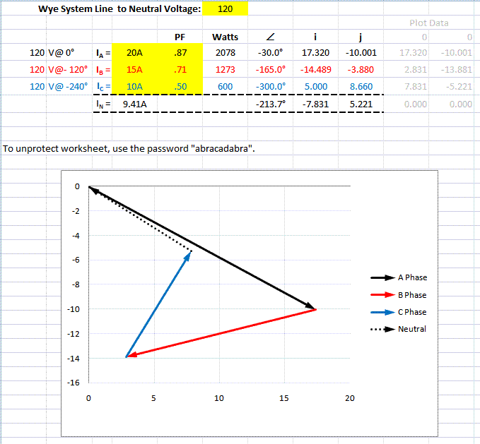
Motor 1 is connected between A phase and neutral and draws 20 amps at .866 pf.

Motor 2 is connected between B phase and neutral and draws 15 amps at .707 pf.

Motor 3 is connected between C phase and neutral and draws 10 amps at .5 pf.

Could someone detail the addition necessary (in polar notation) to resolve the neutral current?

Thanks again.
bb

First, we assign phase angles of 0, -120, -240 to Va, Vb, and Vc

Since the loads are motors, we assume lagging currents which lag the applied voltages by 30, 45, and 60 degrees. Then the load currents flowing into the neutral are,

Ia = 20A @ -30 = 10A[cos(-30) + jsin(-30)]
Ib = 15A @ -165 = 15A[cos(-165) + jsin(-165)]
Ic = 10A @ -300 = 10A[cos(-300) + jsin(-300)]

If we assume that all currents flow into the neutral,

In = - [Ia + Ib + Ic]

For a numeric solution, we simply substitute values for the sines and cosines, sum up the real and imaginary terms separately and convert back to polar form.

Don't forget the negative sign!
 
Could someone detail the addition necessary (in polar notation) to resolve the neutral current?

Had it all typed out but my browser first froze for about 10 minutes then crashed. I was in the middle of uploading a revised excel neutral calculator :mad:

The revised calculator gives the results depicted below...

neutralcurrent-1.gif


I see rattus managed to posted in the meantime. My version was similar... but not ;)

It started...
Ia + Ib + Ic + In = 0

In = – (Ia + Ib + Ic)​
...so we don't have to assume anything about which way the neutral current is flowing, and values can be plugged directly into this formula.

Additionally, it needs noted that...
acos(pf) = ɸ
...which is the phase angle difference between line voltage and line current. The polar notation of line currents takes the form I@(θ–ɸ), where θ is the phase angle of the voltage, and ɸ is subtracted from it because motor current waveforms lag the applied voltage waveform.
 
Last edited:
Static and rotating phasors:

Static and rotating phasors:

There seems to be widespread confusion between fixed and rotating phasors, and at one time I had a reference which discussed both. I will search for said reference.

For those confused about the difference between static (fixed) and rotating phasors, this link provides a bit of clarification:

http://books.google.com/books?id=av...=X&oi=book_result&resnum=3&ct=result#PPA58,M1

BTW, in the USA, the convention is to measure phase angles CCW from the positive real (horizontal) axis in the complex plane.
 
For those confused about the difference between static (fixed) and rotating phasors, this link provides a bit of clarification:

http://books.google.com/books?id=av...=X&oi=book_result&resnum=3&ct=result#PPA58,M1
IMO, that text will not clarify anything for the majority of viewers :grin:

BTW, in the USA, the convention is to measure phase angles CCW from the positive real (horizontal) axis in the complex plane.
Please put that in trade terms...

Va @ ___?
Vb @ ___?
Vc @ ___?

...and a lagging current would have a phase angle greater than or less than that of the voltage?
 
IMO, that text will not clarify anything for the majority of viewers :grin:


Please put that in trade terms...

Va @ ___?
Vb @ ___?
Vc @ ___?

...and a lagging current would have a phase angle greater than or less than that of the voltage?

True. I just stuck that in for the benefit of some hypercritical critics.

The angles are arbitrary as long as the separation is 120 degrees. I prefer 0, -120, and -240 which yields a sequence of ABC. If I swap two of the angles, the sequence is reversed--the sequence is CBA. Whatever the sequence may be, the voltage with the more negative angle follows the voltage with the more positive angle. The rotating phasor still rotates CCW, and positive angles are still measured CCW relative to the positive real axis. We should however forget rotating phasors and concentrate on the fixed phasors in order to obtain the steady state solution.

Lagging current will always carry a negative angle relative to the angle of the applied voltage.
 
We should however forget rotating phasors and concentrate on the fixed phasors in order to obtain the steady state solution.

I understand the difference. However, one must understand at least the basic concept of rotating phasors before they can understand the circumstances which permit us to use a static model. Without that understanding, it just looks like a few lines with arrows!!!
 
Wow, many thanks for the updated spreadsheet.

Now to demonstrate another problem of mine.

It is my understanding that I should get the same resulting neutral current regardless of the phase sequence of the loads.

With your spreadsheet, I swap the A phase and the B phase load and I get a totally different neutral current.

Am I wrong in my thinking?

BTW, I appreciate all of the efforts to answer my questions, you are clarifying the theory considerably for me (and hopefully others)
 
Status
Not open for further replies.
Top