neutral current calculation....again

Status
Not open for further replies.
Am I wrong in my thinking?

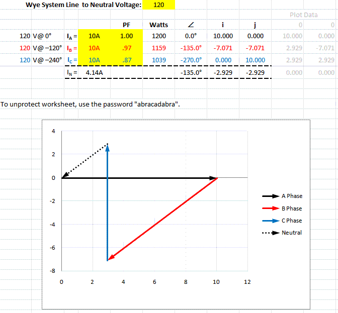
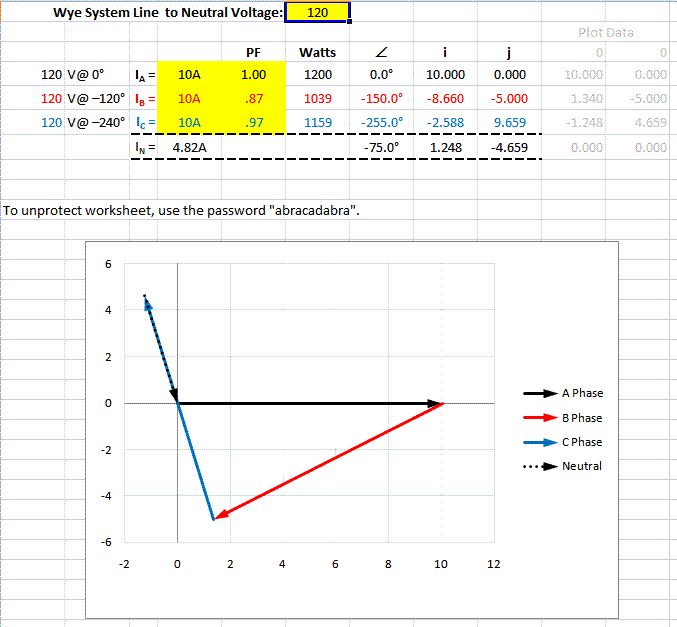
Not in one sense... and that is, if all three loads exhibited the same power factor, the magnitude of the neutral current would not change when changing the sequence of the loads. In all other cases, where the loads exhibit at least one differing power factor, the neutral current's magnitude will likely change.
 
Thank you very much $mart. I feel a little vindication on this issue.

I have been discussing this with my colleagues at our institution and I was of the same mind as you.

The rest of the group insisted that the neutral current is required to be the same, regardless of phase sequence.

I'm pretty sure that there are other instructors (apprentice) that have the same thought as my colleagues!

Since this is such a common installation , 3p - 4w wye, with single phase loads at differing power factors, I appreciate the clarity.

Is there general consensus on this fact within the forum??

The magnitude of the neutral current is independent of phase sequence. I would expect the phase angle to change though if the sequence is reversed.
 
Thanks for the comment rattus.

So, it is your thought that the neutral current should NOT change if I change the phase sequence on the loads?

This is the same discussion I am having with my colleagues.

If I could detail how I calculate my values....

First, I draw the phase voltage vectors.
Then I calculate the phase angles for the different single phase loads.
Then I plot the current vectors (usually) lagging the phase voltage vectors.

I now have six vectors on my paper.

I erase the phase voltage vectors and I am left with the three current vectors and their angular displacements from each other. Of course, they are not 120 degrees apart since each single phase load has a different pf.

I now add all three vectors to find my neutral current.

Then, using the same values for the loads, I swap the phase voltage connection for two of them and redo my simple analysis.

I get two different neutral currents.

What am I doing wrong in this analysis?

(I do appreciate the dialogue)
 
Bill, You may be right for the case of differeing PFs. Give us your problem and results, and we will make a comparison.
 
Ok....I'll use the example from before

Motor 1- A phase and neutral - 20 amps at .866 pf.

Motor 2- B phase and neutral - 15 amps at .707 pf.

Motor 3- C phase and neutral - 10 amps at .5 pf.

This results in a neutral current of 9.41 amps.


Changing the order to


Motor 1- A phase and neutral - 15 amps at .707 pf.

Motor 2- B phase and neutral - 20 amps at .866 pf.

Motor 3- C phase and neutral - 10 amps at .5 pf.

This results in a neutral current of 12.07 amps.

Curious, no?
 
What am I doing wrong in this analysis?

Nothing :grin:

When you reverse the connection sequence (ABC to CBA) you would only get the same neutral current if by some magical method could also change the current's phase angle to lead, rather than lag, the applied voltage by the same amount... which btw retains the same power factor.

Since there is no magical method (at least none that is practical), you have 3 motors and six possible ways to connect them each on one of three phases: ABC, BCA, CAB and CBA, BAC, ACB. Three of those possible connection will have the same resultant magnitude of neutral current while the other three will be different.

The only circumstance under which all six possible connection schemes will have the same magnitude of neutral current is when all three motors exhibit an identical (lagging) power factor.
 
Last edited:
Me too:

Me too:

Ok....I'll use the example from before

Motor 1- A phase and neutral - 20 amps at .866 pf.

Motor 2- B phase and neutral - 15 amps at .707 pf.

Motor 3- C phase and neutral - 10 amps at .5 pf.

This results in a neutral current of 9.41 amps.


Changing the order to


Motor 1- A phase and neutral - 15 amps at .707 pf.

Motor 2- B phase and neutral - 20 amps at .866 pf.

Motor 3- C phase and neutral - 10 amps at .5 pf.

This results in a neutral current of 12.07 amps.

Curious, no?

I get the same results. Try plotting the current phasors for a picture of the difference.

Has to do with the asymmetry of the phasors. If the PFs are are equal, I think In would not change.
 
Happy at last!

Happy at last!

Thanks Smart$ and rattus.
I agree with your assessments.

We are agreed then, that neutral current can be different, depending on phase sequence, as long as the single phase power factors are different.

I may even do a lab on the subject to verify, but I'm am fully confident that we have resolved this issue!

As always, many heads are better than one.

If anyone else has comments, I'm happy to hear them but I consider my question answered.

Thanks again, to all who contributed.
 
Okay, it does'nt really matter if the angle is positive or negative for the calculation. Here's the formula used for power factor:

P.F. = cosine(45) = cosine(-45) =.707

The results are the same for both a positive and negative angle.
 
Okay, it does'nt really matter if the angle is positive or negative for the calculation. Here's the formula used for power factor:

P.F. = cosine(45) = cosine(-45) =.707

The results are the same for both a positive and negative angle.

For power factor it doesn't matter... but in circuit analysis using phasors and/or vector math we use angles only... so we do need to know whether those angles are positive or negative and relative to what reference.
 
A simpler way:

A simpler way:

BTW, there is a simpler formula for In which applies if the currents are separated by 120 degrees. I don't recall it offhand, but Smart will.
 
BTW, there is a simpler formula for In which applies if the currents are separated by 120 degrees. I don't recall it offhand, but Smart will.

:rolleyes::grin:

You mean this one:
In = √(Ia? + Ib? + Ic? ? Ia∙Ib ? Ib∙Ic ? Ia∙Ic)​
Its result is only valid with loads having an identical φ values (i.e. current phase angles are displaced by 120?; unity power factor)
 
Just a comment on the topic of vector addition (or subtraction for that matter).
I have discovered a great calculator for doing direct entry vector math.
Maybe I'm the last guy to discover it but the one I use and recommend to my students is the Sharp EL-520 or 540 ..... priced very low for my students but very adapted to electrical calculations.

Once my students have a good understanding of the fundamentals of vector theory I encourage them to use the power of the calculator to help them with our limited time for training.

I will put this comment in the instructors section but since we have done so much on the topic, I thought I would share my thoughts on this.
 
:rolleyes::grin:

You mean this one:
In = √(Ia? + Ib? + Ic? ? Ia∙Ib ? Ib∙Ic ? Ia∙Ic)​
Its result is only valid with loads having an identical φ values (i.e. current phase angles are displaced by 120?; unity power factor)

Looks right to me.

You can check this easily by letting all currents be equal, and you can check it again by letting two be equal and letting the third be zero. Results should be obvious.

Don't overlook the square root sign.
 
I'm on my way out the door.
If someone hasn't responded sufficiently, when I get back I'll do it.

Smart,

Some of the guys are more Electricians (visual & CCW)
than Math experts (conceptual where A+B+C = 0).

I work with both types, and it gets the job done.

I can use the Calculator either way.
Thanks for the effort building the Calculator.
 
Effect of Phase Sequence on In:

Effect of Phase Sequence on In:

Smart, why don't you give us a graphic example of the effect of phase sequence on neutral current. That is, add these phasors graphically.

For example, relative to the applied voltage:

Ia = 10A @ 0
Ib = 10A @ -15
Ic = 10A @ -30

Then for sequence ABC,

Ia = 10A @ 0
Ib = 10A @ -135
Ic = 10A @ - 270

And for sequence ACB,

Ia = 10 @ 0
Ic = 10 @ -150
Ib = 10 @ -255
 
...for sequence ABC,

Ia = 10A @ 0
Ib = 10A @ -135
Ic = 10A @ - 270

neutralcurrent2.gif


...for sequence ACB,

Ia = 10 @ 0
Ic = 10 @ -150
Ib = 10 @ -255

Example depicted below puts your Ic as Ib, and your Ib as Ic. I'm assumming you are swapping loads and not changing power factors :)

neutralcurrent3.gif
 
Last edited:
Status
Not open for further replies.
Top