I concur :smile:crossman said:...since the service neutral has to be sized based on the maximum unbalanced load, we're okay.
You are using an out of date browser. It may not display this or other websites correctly.
You should upgrade or use an alternative browser.
You should upgrade or use an alternative browser.
Neutral Current Calculation
- Thread starter tallgirl
- Start date
- Status
- Not open for further replies.
tallgirl
Senior Member
- Location
- Glendale, WI
- Occupation
- Controls Systems firmware engineer
crossman said:Back to the original thought of the OP:
After having pondered this a good bit more, I still hold the conclusion that, considering normal residential loads, there is no way to overload a properly sized service neutral conductor regardless of the loading. There just aren't any scenarios where the service neutral carries more current than the unbalanced load.
And since the service neutral has to be sized based on the maximum unbalanced load, we're okay.
Ah, but now you're starting to get into the domain of the real problem.
The service neutral is sized for the maximum unbalanced LOAD, per 220.61. There is no discussion in here about anything but LOAD and the problem isn't LOAD. And 690.8 says nothing about sizing neutral conductors to carry the sum of the greatest LOAD and the greatest SUPPLY. My guess is that Article 220 hasn't caught up with Article 690 yet.
So, we're back to which section explicitly states that the neutral conductor in a grid-interactive solar power system must be sized to carry the sum of the greatest LOAD and greatest SUPPLY.
- Location
- Massachusetts
tallgirl said:which section explicitly states that the neutral conductor in a grid-interactive solar power system must be sized to carry the sum of the greatest LOAD and greatest SUPPLY.
240.4 :wink:
tallgirl
Senior Member
- Location
- Glendale, WI
- Occupation
- Controls Systems firmware engineer
gar said:080712-2149 EST
crossman:
I am not sure how your comment on code compliant fits into the description I provided.
From hot line 1 to neutral I have a load that draws current from 80 to 85 degrees with a peak value of I1. Assume it to be a rectangular pulse. This dissipates I1^2*Rneutral*5/360 watts.
From hot line 2 to neutral I create an identical pulse but delayed to occur between 95 to 100 degrees and of opposite polarity. Clearly these do not overlap and therefore do not cancel. This second pulse dissipates the same power in the neutral as the first pulse.
Thus, if we assume the neutral wire size is the same as either hot line, then the power dissipated in the neutral is double that in either hot line. Note: power dissipation has nothing to do with the polarity of the current when the different currents do not overlap.
This is something I could create. Why? I have no idea for a use other than to prove that in a center tapped single phase application that I can produce a higher neutral current than the current in either hot line.
I disagree with your assertion that the current would be higher, especially since you stipulated that they do not overlap. If there is no overlap, L1 = N or L2 = N. There's never a situation, because there is no overlap, where N = L1 + N.
And so what if the power in N is twice L1 or L2 -- that's irrelevant to the current in N and it's relationship to the maximum ampacity N was sized to carry.
Here's a much easier scenario -- you have a half-wave rectifier between L1 and N, and between L2 and N. The outputs of both rectifiers are driving 180 degree loads at maximum rated capacity during each legs' positive cycle. What is the LOAD on N? Not the load on N relative to L1 and L2, what is the actual value of the load on N?
tallgirl
Senior Member
- Location
- Glendale, WI
- Occupation
- Controls Systems firmware engineer
iwire said:240.4 :wink:
I disagree. Were does it say how to calculate the maximum neutral current? My 2008 is at the office, but the 2005 says nothing about sizing conductors in 240.4 and it says nothing about calculating the maximum current on the neutral conductor OR using an OCPD on one, and table 240.4(G) really doesn't say anything because it doesn't mention sizing conductors associated with AC inverters.
- Location
- Massachusetts
tallgirl said:I disagree. Were does it say how to calculate the maximum neutral current?
I know as well as you do that it does not say that.

But it does require us to protect conductors at or below their ampacity, how that is accomplished is largely irrelevant to that section.
I could have also pointed out 310.10.
tallgirl
Senior Member
- Location
- Glendale, WI
- Occupation
- Controls Systems firmware engineer
iwire said:I know as well as you do that it does not say that.
But it does require us to protect conductors at or below their ampacity, how that is accomplished is largely irrelevant to that section.
Okay, so how do I size the neutral conductor so I don't have to use an OCPD on the neutral the same as the last few million 120/240 single phase panels that were installed didn't have an OCPD on their neutrals?
If you want to admit that it doesn't say how to size the neutral conductor, how do I write one of those ROP thingies for the 2011 NEC? I've seen a number of installs now where L1, L2 and N are all sized exactly the same and if that's wrong (and I believe it is), someone should say so. There were all inspected installations, and I wouldn't have thought twice about it, but that I'm writing solar system monitoring software and that situation came up.
I could have also pointed out 310.10.[/QUOTE]
Are you using the 2008 NEC? I think mine is at the office, and it being Sunday I don't want to have to go to the office.
The 2005 NEC has over temperature protection for 310.10. Or am I under caffeinated?
JohnJ0906
Senior Member
- Location
- Baltimore, MD
tallgirl said:Are you using the 2008 NEC? I think mine is at the office, and it being Sunday I don't want to have to go to the office.
The 2005 NEC has over temperature protection for 310.10. Or am I under caffeinated?
'08 NEC
......
tallgirl
Senior Member
- Location
- Glendale, WI
- Occupation
- Controls Systems firmware engineer
JohnJ0906 said:
Cool! Hey, that's a letter easier to use than the 2008 NEC I paid real money for.
But it's still the section on temperature limitations of conductors
And on that note, I need coffee ...
220.61 Feeder or Service Neutral Loadtallgirl said:W[h]ere does it say how to calculate the maximum neutral current?
"...maximum unbalanced load as determined by this article. ..."
Table 220.3 lists Article 690 as an Additional Load Calculation Reference.
Current on any line, including the Neutral conductor, is synonymous with having a connected load... and should be considered accordingly. In the case of "sell" current, the load is not on the premises... but the current source is and so are the conductors which carry that current.
- Location
- Massachusetts
tallgirl said:But it's still the section on temperature limitations of conductors
Yes it is.
It is a violation to run conductors hotter then designed. That is not restricted to just the ambient temp.
If the design of the electrical system allows the possibility of overloading the neutral then it is also likely the design will allow a violation of 310.10
There is nothing wrong with stretching the code as long as we don't make new rules up.
BTW did you miss the :wink: wink in my first post in this thread?
gar
Senior Member
- Location
- Ann Arbor, Michigan
- Occupation
- EE
080713-1811 EST
tallgirl:
Because the neutral is the same size wire, then its resistance is the same as either hot line. Turn load 1 off and the neutral will have the same power dissipation as the hot line. Since I specifically created loads that have non-overlapping current pulses in the neutral it means the the power dissipation in the neutral is double that of one hot line when both loads are on, and the neutral temperature rise will be about double that of one hot line.
The shape of my waveforms has nothing to do with power dissipation if the current measurement of a hot line is RMS.
For my example the RMS value of the composite neutral waveform is 1.414 times the current of one hot line.
A half wave rectified current in a resistive load provides 1/2 the power of a full wave current (rectified or not). The RMS current of a half wave is thus 0.707 of a full wave. If you have a resistance of R in series with each transformer lead, then you have the same result as I described with the double pulse in 1/2 cycle. The resistor R to the center tap has double the power dissipated as either of the outer resistors.
crossman:
I answered you question of peakiness above. I am basing the analysis on RMS current. The only reason for the narrow peak was to provide an easy illustration that would separate the two components.
The full wave rectified example above does the same thing with less peaking.
.
tallgirl:
If both hot lines and the neutral are the same material and wire size, then the resistance of each of those wires is the same, and the temperature ratings will be the same. If the hot lines are sized for their load RMS current, then the power dissipation in one of those lines is = I^2*R.And so what if the power in N is twice L1 or L2 -- that's irrelevant to the current in N and it's relationship to the maximum ampacity N was sized to carry.
Because the neutral is the same size wire, then its resistance is the same as either hot line. Turn load 1 off and the neutral will have the same power dissipation as the hot line. Since I specifically created loads that have non-overlapping current pulses in the neutral it means the the power dissipation in the neutral is double that of one hot line when both loads are on, and the neutral temperature rise will be about double that of one hot line.
The shape of my waveforms has nothing to do with power dissipation if the current measurement of a hot line is RMS.
For my example the RMS value of the composite neutral waveform is 1.414 times the current of one hot line.
I have no idea what this paragraph means. I created an example with a single pulse in each hot line, each with the same value of RMS current, and the pulses were non-overlapping. Thus, the composite current in the neutral consists of two pulses, and this of necessity increases the RMS current in the neutral.I disagree with your assertion that the current would be higher, especially since you stipulated that they do not overlap. If there is no overlap, L1 = N or L2 = N. There's never a situation, because there is no overlap, where N = L1 + N.
This example creates a full-wave center tapped rectifier with a full wave rectified current in the neutral.Here's a much easier scenario -- you have a half-wave rectifier between L1 and N, and between L2 and N. The outputs of both rectifiers are driving 180 degree loads at maximum rated capacity during each legs' positive cycle. What is the LOAD on N? Not the load on N relative to L1 and L2, what is the actual value of the load on N?
A half wave rectified current in a resistive load provides 1/2 the power of a full wave current (rectified or not). The RMS current of a half wave is thus 0.707 of a full wave. If you have a resistance of R in series with each transformer lead, then you have the same result as I described with the double pulse in 1/2 cycle. The resistor R to the center tap has double the power dissipated as either of the outer resistors.
crossman:
I answered you question of peakiness above. I am basing the analysis on RMS current. The only reason for the narrow peak was to provide an easy illustration that would separate the two components.
The full wave rectified example above does the same thing with less peaking.
.
crossman
Senior Member
- Location
- Southeast Texas
tallgirl said:Ah, but now you're starting to get into the domain of the real problem. The service neutral is sized for the maximum unbalanced LOAD, per 220.61. There is no discussion in here about anything but LOAD and the problem isn't LOAD
Tallgirl, you missed what I was saying. Please allow me to clarify:
I calculated about 30 various scenarios involving a 120/240 single phase service, inverters of various sizes, and various loads. I could produce no results where the service neutral was carrying anything more than the unbalanced load, even in what seemed to be worst-case scenarios.
My only assumption was that the inverter maintained equal current output on both line conductors. I think this is true of typical inverters. As long as the currents produced on each leg of the inverter are about the same amount, the inverter, in reality, does not even contribute to the unbalanced current. This may seem strange based on your original problem presented in your original post, where 5 + 5 made 10. But really what is happening is the inverter current is flowing right through the inverter from 1 leg to the other. The unbalanced load current is what is flowing on the service neutral.
The only scenario in which the neutral was overloaded was with a large current capacity output inverter, and a large difference in output current on one leg as compared to the other leg from the inverter. This scenario involved an inverter which was much larger than what is typical in a residential application with solar panels on the roof or in the backyard.
So, the answer is, at least in my mind, that a typical residential solar power system has no possibility of overloading the service neutral. Now, all this is speculation based on my knowledge of electrical theory. I haven't done any research here.
It is certainly an interesting subject, and I am surprised that none of the other "theoretical" forum members have jumped on this.
And just so we are clear, I'll say it again: An inverter with an equal output current on both output legs will contribute absolutely zero current on the service neutral.
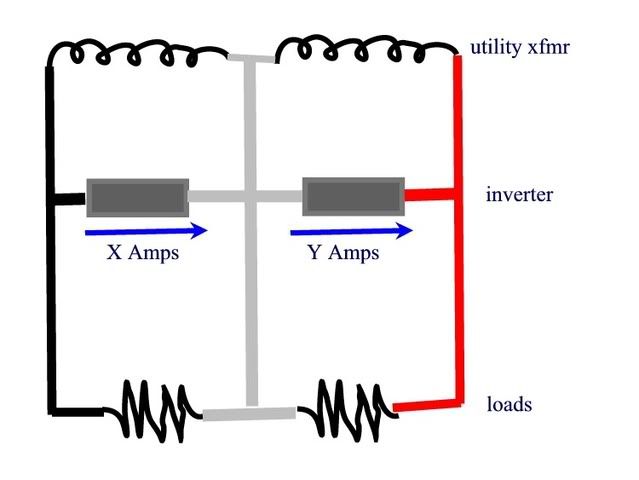
Look at the diagram below.
It is straightforward to see that as long as the current from each leg of the inverter is substantially the same, then, by Kirchoff's current law, the only current in the service neutral is the unbalanced load. The inverter does not contribute to the neutral current, even though our intuition says that it does.
If X amps = Y amps then the only current flowing out of the junction between the inverters will be equal to the unbalanced load. The inverter current has nothing to do with it.
crossman
Senior Member
- Location
- Southeast Texas
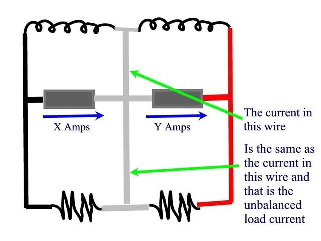
One more just to clarify:
crossman
Senior Member
- Location
- Southeast Texas
gar said:crossman:
I answered you question of peakiness above. I am basing the analysis on RMS current. The only reason for the narrow peak was to provide an easy illustration that would separate the two components.
The full wave rectified example above does the same thing with less peaking.
Yes. What I was thinking earlier was that the worst case scenario would be one load conducting for the first quarter-cycle, then the other load conducting on the second quarter-cycle and on and on.

crossman
Senior Member
- Location
- Southeast Texas
That is an excellent diagram showing a "single face" system, as opposed to "three face" as diagramed below:
:roll: :roll: :roll:
:roll: :roll: :roll:
gar
Senior Member
- Location
- Ann Arbor, Michigan
- Occupation
- EE
080714-0806 EST
crossman:
Your analysis of post #53 is a very good way to look at the real world operation.
.
crossman:
Your analysis of post #53 is a very good way to look at the real world operation.
.
ELA
Senior Member
- Occupation
- Electrical Test Engineer
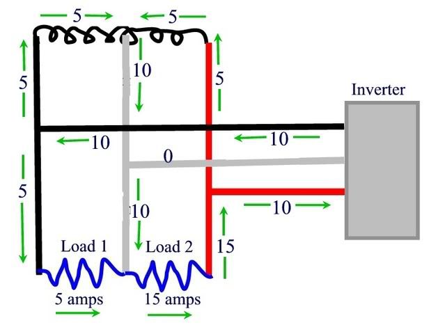
crossman said:Here are my thoughts on current directions. This, of course, is for one half of the sine wave, for the other half, just reverse all the arrows.
The black leg from the utility is 5 amps SELL and the red wire from the utility is 5 amps BUY.
I do not understand this concept of 5 amps sell and 5 amps buy?
Wouldn't it really be that the primary of the transformer would just see a lessor demand by the amount of the load that the inverter was taking up?
We do not really have two independent sources from the utility do we?
(yes two secondary coils but only one primary)
I was having a hard time with the diagram since it shows a total load of 2400watts load and the inverter providing 2400 watts load power. This would imply a net of zero from the utility ?
I know little about dual leg inverters, do they really have to supply equal currents on both legs (if they have a neutral as shown)?
I envisioned a diagram where the load currents are as shown but the inverter supplies 5 amps on one leg, 10 amps on the other leg, 5 amps on its neutral, 10 amps on the load neutral and 5 amps on the utility supply neutral.
This way the utility supplies 600 watts of the load and the inverter supplies 1800watts. Without the inverter there would have been 10 amps on both service legs. With the inverter there is now zero on one leg and 5 on the other.
I would think the inverter legs would supply a variable current on each leg as required up to a current limit point. At that point the utility would then take over.
Of course there could be many different scenarios /current divisions/loads but The concept of buy and sell on the two different legs is confusing to me.
crossman
Senior Member
- Location
- Southeast Texas
ELA said:I do not understand this concept of 5 amps sell and 5 amps buy? Wouldn't it really be that the primary of the transformer would just see a lessor demand by the amount of the load that the inverter was taking up? We do not really have two independent sources from the utility do we?
With everything set up properly, you can actually sell energy back to the utility.
ELA said:I was having a hard time with the diagram since it shows a total load of 2400watts load and the inverter providing 2400 watts load power. This would imply a net of zero from the utility ?
That is correct. We are buying 5 amps on one leg but selling 5 amps on the other, net result is zero. The meter would not be turning.
ELA said:I know little about dual leg inverters, do they really have to supply equal currents on both legs?
As far as I know, they produce the maximum current which is provided by the amount of sun at any given time on both legs.
ELA said:I would think the inverter legs would supply a variable current on each leg as required up to a current limit point. At that point the utility would then take over.
If it is a bright sunny day, and no one is home, and 95% of the load is turned off, why not go ahead and let the inverter produce maximum amps on both legs and sell the energy back to the utility? In effect, the meter turns backwards.
- Status
- Not open for further replies.