? Neutral ? Why do they call it that?

Status
Not open for further replies.
So I gather that if you shove a magnet through a coil it will induce a current in the coil. ~ Faraday.
It further reasons that instead of shoving a magnet you could just shove magnetism back and forth through the coil. ~ Tesla.
I think (speculatively surmise) that the magnetism increases and decreases (alternates) from zero to peak voltage to zero to negative peak then back to zero before beginning the next cycle. I think this is called a phase and if it could be graphed might be called a sine. ` I think.

So in order to transform one voltage into another two coils must be wrapped either end of some conductive loop with the amount of coils being reduced from the primary voltage to the secondary. My broken understanding (speculation) is that the dead center of the secondary coil would continuously be zero voltage no matter which way the current is going because it is continuously the center of the sine. I imagine this would allow returning unbalanced current back into the secondary coil.

Is that why they call they call the grounded conductor the neutral?

Please break down responses as though you were addressing a novice as I need that.
 
My understanding of the whole phase, neutral thing is pretty basic so I think I'm capable of giving a not to complicated answer.

The neutral conductor is the grounded conductor because that is the one we are told to physically connect to earth. There are advantages to doing this- it stabilizes things, gives you a zero volt reference, facilitates clearing a fault, but it's just a point on the winding of the transformer. I could be any point, but it makes the most sense to use the center point most of the time. There is no magic other than that unless you want to get into some math and physics.

Check out this link from a great member who, sadly has not participated in a while, but I think explains things quite nicely...http://forums.mikeholt.com/showthread.php?t=89023&p=708650#post708650
 
So I gather that if you shove a magnet through a coil it will induce a current in the coil. ~ Faraday.
It further reasons that instead of shoving a magnet you could just shove magnetism back and forth through the coil. ~ Tesla.
I think (speculatively surmise) that the magnetism increases and decreases (alternates) from zero to peak voltage to zero to negative peak then back to zero before beginning the next cycle. I think this is called a phase and if it could be graphed might be called a sine. ` I think.
Phase is a relative position on the AC waveform. In slang, it is an AC signal between two terminals. There are more complex versions, slangs, and definitions about individual "phases" and also the relationships between them but don't get hung up on that, at least for this question.

So in order to transform one voltage into another two coils must be wrapped either end of some conductive loop with the amount of coils being reduced from the primary voltage to the secondary. My broken understanding (speculation) is that the dead center of the secondary coil would continuously be zero voltage no matter which way the current is going because it is continuously the center of the sine.
Only if that point is your zero reference point.

I imagine this would allow returning unbalanced current back into the secondary coil.
Not only into the coil but out of the coil as well on alternating half cycles.

Is that why they call they call the grounded conductor the neutral?
It is called the neutral because it is a point close to the average of all the other terminals. This is strictly true for a true "neutral point" but not exactly true for all "neutrals" (like with a high-leg 3-phase or 120/208 single-phase).

The idea of the neutral is to find a point we can tie to Earth such that all other voltages have as low as possible voltage magnitude relative to the Earth tie point (our neutral). As I said, it is not always the exact "neutral point" but that is the initial goal.
 
Is that why they call they call the grounded conductor the neutral?

First, a grounded conductor and a neutral are different things. It just so happens that in North America we ground the neutral on most AC systems so that conductor happens to be both most of the time here.

As for why a neutral is called that: If you add up the instantaneous voltages at any given instant between the neutral and the other conductors, those voltages should add up to zero. I.E.: Pretend you can stop time for an instant. Take your voltage meter, set to DC, and measure from the neutral to each other conductor in the system, keeping the same probe on the neutral. The sum of your readings will theoretically be zero. As mentioned above, this doesn't exactly hold true for some systems (high-leg delta) but that's a matter of which other conductors are considered to count.

Check out the NEC definition of a Neutral as well.

If the neutral is grounded then it will be zero volts to ground. (That is, if you are not far enough from the grounding point to have serious voltage drop, or if you aren't measuring the middle of a lightning strike, or a few other things). If the neutral is not grounded then it may be some other voltage to ground.

How would a Venn diagram look to distinguish the definitions of neutrals and groundED conductors?

Can you give an example of when a conductor is neutral, but not groundED?
Similarly, can you give an example of when a conductor is groundED, but not neutral?

In a bipolar DC system, with a positive ungrounded, equal/opposite negative ungrounded, and grounded conductors, would the grounded conductor be a neutral?
High leg delta's grounded conductor? Is it also a neutral?
Corner grounded delta's grounded conductor?
 
Can you give an example of when a conductor is neutral, but not groundED?
The floating X0 conductor on the primary of a wye-delta. I guess any floating X0 in a wye system really.

Similarly, can you give an example of when a conductor is groundED, but not neutral?
The center-tap "neutral" on a delta bank. It is a neutral point for the 120/240 single-phase system of voltages but not for the 240 3-phase system of voltages.

Add: also a corner grounded 3-wire delta.
 
The floating X0 conductor on the primary of a wye-delta. I guess any floating X0 in a wye system really.

The center-tap "neutral" on a delta bank. It is a neutral point for the 120/240 single-phase system of voltages but not for the 240 3-phase system of voltages.

Add: also a corner grounded 3-wire delta.


So the distinction is as follows:
The grounded conductor is a conductor capable of carrying current and physically built to be at the same voltage as ground.
The neutral is built to be "equidistant" in voltage from all ungrounded current-carrying conductors, with not necessarily any particular relation to the voltage of ground.
 
I think the distinction between groundED and groundING conductor is much more important. I'd rather hear someone use groundED conductor and neutral interchangeably, than mix up those two terms.
But neutral doesn't have to be grounded so the terms aren't really interchangeable.
 
similarly, can you give an example of when a conductor is groundED, but not neutral?

Two wire source, maybe a 480 x 120 volt control transformer. We ground one lead of the secondary but technically it is not a neutral, in fact we can ground either lead and it will still work the same.
 
Cool!!!

Cool!!!

I'm so glad you guys are here to help me learn this confusing stuff.
I know most of us probably don't say thank you to the appropriate degree we benefit but you guys really help people.
Thanks again; especially for the link to Larry Fine's post
 
My understanding of the whole phase, neutral thing is pretty basic so I think I'm capable of giving a not to complicated answer.

The neutral conductor is the grounded conductor because that is the one we are told to physically connect to earth. There are advantages to doing this- it stabilizes things, gives you a zero volt reference, facilitates clearing a fault, but it's just a point on the winding of the transformer. I could be any point, but it makes the most sense to use the center point most of the time. There is no magic other than that unless you want to get into some math and physics.

Check out this link from a great member who, sadly has not participated in a while, but I think explains things quite nicely...http://forums.mikeholt.com/showthread.php?t=89023&p=708650#post708650
"
""Let's take two 1.5-volt bulbs, and connect one from the top of the upper battery to the center tap, and the other from the bottom of the lower battery to the center tap. Each bulb receives 1.5 volts from its battery, and each can be turned on and off independently.


Okay, now we have a conductor, connected to the metallic center tap, that is shared by both of the bulbs. This conductor does indeed qualify as being called a 'neutral'. It also happens to be grounded, but that has no bearing or effect on our circuit.

We could also add a 3-volt bulb, connecting it from the top of the upper battery to the bottom of the lower battery. It can operate independently from the other two bulbs. In fact, we could add a plethora of both 1.5-volt and 3-volt bulbs to our batteries.

If we happen to add matching wattages of 1.5-volt bulbs to the two 1.5-volt halves of our 3-volt system, no current will flow through the wire to the center tap. However, if we have an imbalanced set of loads, the difference current will flow on the neutral.""

I pulled this quote out of this excellent explanation in the link you posted. I just have some questions about it.
Im cruzing along with everything fine until he throws in the "add matching wattages" part. Is this adding the same as three lines earlier with the adding two 1.5 volt bulbs in the same configuration? Does this addition of this word change anything to this explanation? In the configuration with the wattages word, does the bulb light? I ask because he says that "no current will flow to the center tap". Is this because all of the energy is being consumed at the bulb, therefor current goes in but doesn't come out? Again I ask, is this same configuration as three lines earlier?
Thanks again for this.
 
So the distinction is as follows:
The grounded conductor is a conductor capable of carrying current and physically built to be at the same voltage as ground.
The neutral is built to be "equidistant" in voltage from all ungrounded current-carrying conductors, with not necessarily any particular relation to the voltage of ground.
Close enough.
 
Is this adding the same as three lines earlier with the adding two 1.5 volt bulbs in the same configuration?
yes

Does this addition of this word change anything to this explanation?
Not really.

Is this because all of the energy is being consumed at the bulb, therefor current goes in but doesn't come out?
No. All energy is consumed in the bulb either way (except for minor conductor losses). The current goes in and out but just returns differently. In the case with balanced loads, the current travels equally through both. In the unbalanced case, one bulb needs less current than the other so part of the current diverts down the neutral path to return rather than being helpful to the second bulb.

Keep in mind that the battery example is ok but not a great AC example because the current ( movement of charges) doesn't really make a loop like cars on a race track but just oscillates back and forth like a saw blade in order to create a magnetic field which is part of the medium needed in which the energy travels.

Real energy gets consumed. The voltage and current is not consumed as they are just mechanisms used to create the electric and magnetic fields that carry the energy. Voltage and current are kind of like the water carrying the wave energy in that the water is not transported or consumed but just transport the energy. Another example is that air is not transported or consumed by sound but is just a medium needed to transport the sound energy.
 
Close enough.

Is it correct to call the grounded conductor in a bipolar DC system a neutral?

That is, a DC system with a positive voltage conductor (RED), an equal and opposite negative voltage conductor (BLACK or YELLOW), as well as a zero voltage grounded conductor (WHITE or GRAY).
 
"
""Let's take two 1.5-volt bulbs, and connect one from the top of the upper battery to the center tap, and the other from the bottom of the lower battery to the center tap. Each bulb receives 1.5 volts from its battery, and each can be turned on and off independently.


Okay, now we have a conductor, connected to the metallic center tap, that is shared by both of the bulbs. This conductor does indeed qualify as being called a 'neutral'. It also happens to be grounded, but that has no bearing or effect on our circuit.

We could also add a 3-volt bulb, connecting it from the top of the upper battery to the bottom of the lower battery. It can operate independently from the other two bulbs. In fact, we could add a plethora of both 1.5-volt and 3-volt bulbs to our batteries.

If we happen to add matching wattages of 1.5-volt bulbs to the two 1.5-volt halves of our 3-volt system, no current will flow through the wire to the center tap. However, if we have an imbalanced set of loads, the difference current will flow on the neutral.""

I pulled this quote out of this excellent explanation in the link you posted. I just have some questions about it.
Im cruzing along with everything fine until he throws in the "add matching wattages" part. Is this adding the same as three lines earlier with the adding two 1.5 volt bulbs in the same configuration? Does this addition of this word change anything to this explanation? In the configuration with the wattages word, does the bulb light? I ask because he says that "no current will flow to the center tap". Is this because all of the energy is being consumed at the bulb, therefor current goes in but doesn't come out? Again I ask, is this same configuration as three lines earlier?
Thanks again for this.

Current is conserved. It has to be the same everywhere, until it "branches" to multiple paths. It is the voltage that corresponds to the current, which drops across load components.

In a series circuit, current is the same everywhere, and voltage drops add up across components.
In a parallel circuit, each path gets full voltage, and current adds up among the paths to form the grand total current prior to branching.

CAUTION: The wattage rating on a bulb is only valid when the rated voltage is across it. As the name implies, it indicates the power in Watts that will be consumed by the bulb, when operating at rated voltage. If you operate a bulb at reduced voltage, it will output reduced power. You can approximate that the resistance of the bulb will be close to the same, which is (Voltage rating^2)/(Wattage rating), if you were to operate it at a different voltage drop across it.
 
Last edited:
Is it correct to call the grounded conductor in a bipolar DC system a neutral?

That is, a DC system with a positive voltage conductor (RED), an equal and opposite negative voltage conductor (BLACK or YELLOW), as well as a zero voltage grounded conductor (WHITE or GRAY).
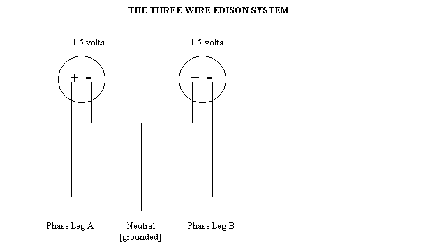
Actually, I believe the term 'neutral' was used on Edison's three wire DC systems and pre-dated the use of the term in AC.

Edit to add:

Here is a drawing of the way an Edison 3 wire circuit is set up. Except Edison used higher voltages for DC distribution. Like 110/220.

edison3.gif


Now as you can see, the far left conductor is connected to the positive side of the DC source, so there is no question, it's positive. The far right side is connected to the negative conductor, so it's obviously negative. But what to call the center conductor? It's connect to both a positive and a negative so it can be one or the other. I think Edison used the term 'neutral' to have a name for the center positive/negative conductor. That's just my thoughts.
 
Last edited:
Is it correct to call the grounded conductor in a bipolar DC system a neutral?
I suppose you could although it is a different system than is being discussed. We have a neutral point midway between magnet poles. A neutral point in a dipole. Etc.
 
Status
Not open for further replies.
Top