Robbierobdude
Member
- Location
- NJ
- Occupation
- Electrical contractor
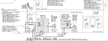
Hello all, I'm a electrical contractor that's doing my first fire pump job. I have never had the opportunity to do one before or even work on one in the past. Attached is the drawing provided to me. I'm concerned about a few things.
1- The service is done in (4-#1 cu wires) to a 400A CT cabinet. I'm assuming its a 125A service feeding the pump controller and jockey pump.?
2- The contractor does not want the floor cut. This means the wiring from the CT will be above ground. I'm thinking the wires will now need to be fused before entering the building. Could some one confirm what size each fused disconnect would be?
I also attached my drawing of how I think it should be done. I appreciate any advice on this as I'm also trying to watch as may videos and read up on this as much as I can. Sometimes you have to just jump right in and learn the hard way.