You missed 240v.... We have 480v 277v 208v 120v panels. ...

You missed 240v.... We have 480v 277v 208v 120v panels. ...
You missed 240v.
Have at it....... Since the OP seems like a good sport, shall we tell him how to determine this with a volt meter?
You missed 240v.
Yep.
It would be interesting to see what the 240 panel really is though and why it is there. And does it come that way from the service. Could be 240Y/139, 240/120 delta center tapped or far more unlikely 240 delta ungrounded or 240 delta corner grounded. Since the OP seems like a good sport, shall we tell him how to determine this with a volt meter?
Well it looks like a separately derived system. I wonder if it is properly bonded to ground. A check of voltage from each phase to ground would be telling.
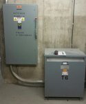
Any conductors connected to A phase in that panel are required to be identified as grounded conductors....white or gray.This is the feeder panel and transformer, have not opened but this is what I will shut off tomorrow to work in the 240V panel, so I could.
Any conductors connected to A phase in that panel are required to be identified as grounded conductors....white or gray.
Any conductors connected to A phase in that panel are required to be identified as grounded conductors....white or gray.
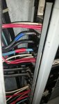
But we do see some.I was able to remove the face panel and sneak a peek inside, snapped a few pictures and this is one:
I don't see much white or gray at all...?
But we do see some.
That's better than none. :happyyes:
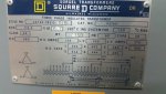
The disconnect says that A phase is grounded. This is a corner grounded system. The conductor connected to A phase is a grounded conductor and the rules in Article 200 apply.Well this is new to me. Can you or anyone else explain further? :?
Check voltages per Don's post.Although the ones that are there go into the other panel, looks like they are a type of gfi breaker with a neutral connection?
I believe the breakers in the panel are labeled "shunt trip" also
This is the feeder panel and transformer, have not opened but this is what I will shut off tomorrow to work in the 240V panel, so I could.
The disconnect says that A phase is grounded. This is a corner grounded system. The conductor connected to A phase is a grounded conductor and the rules in Article 200 apply.
To be sure that you really have a grounded system, you need to check the voltages. If A phase is grounded you will have the following voltages.
A to Ground = 0
B to Ground = 240
C to Ground = 240
A to B = 240
B to C = 240
A to C = 240
Was just able to finally check, checked off of a 3 pole breaker: top lug=245 middle lug=0 bottom lug=247
It appears corner grounded (assuming the values posted are line to ground) and using a 3Ø bus panel... but that doesn't tell you which phase is grounded. The middle lug of a 3P breaker can be positioned in the panel to connect to any one of the three busses.Was just able to finally check, checked off of a 3 pole breaker: top lug=245 middle lug=0 bottom lug=247
hmy::blink: